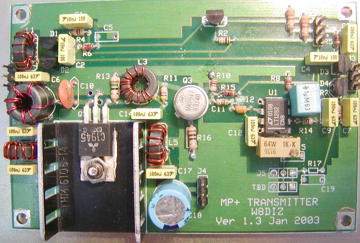
INSTRUCTIONS FOR BUILDING THE XMTR, A component of the multiPIG+
updated 02/22/03 5:00 PM
The XMTR kit includes the following:
1. XMTR PCB
2. Plastic bag with parts
3. Heat Sink
4. Schematic
We will build the BPF in this order:
0. Review instructions. Inspect PCB and parts.
1. Install ALL resistors.
2. Wind and install all toroids.
3. Istall PA and heat sink
4. Instrall all semiconductors
5. Install all capacitors
6. Install headers
Ready...set...begin!
NOTE: We are installing version 1.5 of the XMTR
into PCB version 1.3 so there are some mods!
INVENTORY all the parts against the parts list.
INSTALL ALL RESISTORS:
NOTE: R17 is not installed
____ R16 10 BROWN-BLACK-BLACK 1/4W
____ R13 15 BROWN_-GREEN-BLACK 1/4W
____ R12 51 GREEN-BROWN-BLACK
____ R14 51 GREEN-BROWN-BLACK
____ R10 200 RED-BLACK-BROWN
____ R1 330 ORANGE-ORANGE-BROWN
____ R3 330 ORANGE-ORANGE-BROWN
____ R4 470 YELLOW-VIOLET-BROWN
____ R7 470 YELLOW-VIOLET-BROWN
____ R11 470 YELLOW-VIOLET-BROWN
____ R5 1K BROWN-BLACK-RED
____ R6 1K BROWN-BLACK-RED
____ R15 1K BROWN-BLACK-RED
____ R18 1K or 500 ohm YELLOW POT
If you get a 1K pot, cleanly break off the left or right pin on the pot.
If you get a 500 ohm pot, break off the pin on the screw side of the pot.
Insert the two remaining pins into the left most holes at Q4.
These next resistors are easy to mix up. Just as Ken W4DU.
____ R8 3K ORANGE-BLACK-RED
____ R9 3K ORANGE-BLACK-RED
____ R2 10K BROWN-BLACK-ORANGE
WIND AND INSTALL TOROIDS:
____ L1 FT37-43 10Turns #27 (7" # 27 ga)
____ L4 FT37-43 10Turns #27 (7" # 27 ga)
____ L5 FT37-43 10Turns #27 (7" # 27 ga)
____ L3 FT37-43 10T:3T #27 (7" # 27 ga) & (4" # 27 ga)
 ____ L2 XFMR-BIFILAR 6T
This Xfrm is the equivalent of 4 FT37-43 toroids stacked and glued
The actual part is 2 large ferrite beads from Fair-Rite that
are pre-glued and ready for winding.
____ L2 XFMR-BIFILAR 6T
This Xfrm is the equivalent of 4 FT37-43 toroids stacked and glued
The actual part is 2 large ferrite beads from Fair-Rite that
are pre-glued and ready for winding.
 RunĀthe twisted pair wire through the hole down thru the top. Then wind
the wires around the toroid CW as you look down on it.ĀAfter you have
evenly spaced 6 turns thru the toroid, you should have both ends pointing
down. Strip the insulation on the 4 wires all the way to the body of the
toroid. Take the brown wire from one pair and the red wire from the other
pair and slightly twist them together. Align the wires so that the dual
color connected pair connects to C10, one wire to C6 and the remaining
wire to C13. Solder and check continuity with an ohm meter. You should
find a shorted connection from the collector of Q2 to the right side of
C6 and the right side of C13.
INSTALL ALL SEMICONDUCTORS:
NOTE: Q4 is not installed
____ D1 MPN3700 PIN Diode
____ D2 MPN3700 PIN Diode
____ D3 MPN3700 PIN Diode
____ D4 MPN3700 PIN Diode
____ Q1 2N3906
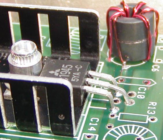
____ Q2 2SC1945 + Heat Sink. Install Q2 as shown in the pictures.
Note 1: The TAB and center lead from the 2SC1945 is the Emitter.
The Heat sink and the 2SC1945 TAB do not need to be insulated
from one another.
Note 2: The extra holes by the PA transistor are for mounting
other transistors that have the center pin connected to the
collector. If you use such a transistor, you WILL have to
insulate the TAB from the heat sink.
____ Q3 MRF517
____ U1 LT1252
INSTALL ALL CAPACITORS:
NOTE: C5, C15 and C19 are not installed
____ C10 100p
____ C1 C2 C4 10n
____ C11 100n Axial
____ C3 C6 C7 C9 C12 C13 C14 C16 C17 100n Radial
____ C8 1u
This cap fits (hangs) above some other parts.
____ C18 470uF
____ C20 43p bottom of PCB
Solder across R11 on bottom of PCB
RunĀthe twisted pair wire through the hole down thru the top. Then wind
the wires around the toroid CW as you look down on it.ĀAfter you have
evenly spaced 6 turns thru the toroid, you should have both ends pointing
down. Strip the insulation on the 4 wires all the way to the body of the
toroid. Take the brown wire from one pair and the red wire from the other
pair and slightly twist them together. Align the wires so that the dual
color connected pair connects to C10, one wire to C6 and the remaining
wire to C13. Solder and check continuity with an ohm meter. You should
find a shorted connection from the collector of Q2 to the right side of
C6 and the right side of C13.
INSTALL ALL SEMICONDUCTORS:
NOTE: Q4 is not installed
____ D1 MPN3700 PIN Diode
____ D2 MPN3700 PIN Diode
____ D3 MPN3700 PIN Diode
____ D4 MPN3700 PIN Diode
____ Q1 2N3906
____ Q2 2SC1945 + Heat Sink. Install Q2 as shown in the pictures.
Note 1: The TAB and center lead from the 2SC1945 is the Emitter.
The Heat sink and the 2SC1945 TAB do not need to be insulated
from one another.
Note 2: The extra holes by the PA transistor are for mounting
other transistors that have the center pin connected to the
collector. If you use such a transistor, you WILL have to
insulate the TAB from the heat sink.
____ Q3 MRF517
____ U1 LT1252
INSTALL ALL CAPACITORS:
NOTE: C5, C15 and C19 are not installed
____ C10 100p
____ C1 C2 C4 10n
____ C11 100n Axial
____ C3 C6 C7 C9 C12 C13 C14 C16 C17 100n Radial
____ C8 1u
This cap fits (hangs) above some other parts.
____ C18 470uF
____ C20 43p bottom of PCB
Solder across R11 on bottom of PCB
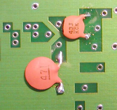 ____ C21 470p bottom of PCB
Solder across R16 on bottom of PCB
INSTALL THE HEADERS:
NOTE: J5 is not installed
____ J1 J2 J3 J4 J-3PIN
TESTING:
Here are some XMTR voltage and power measurements. The V p-p was measured on
the right side of R14 or the junction of R14 and C9. I soldered a small wire
on the right side of R14 on the top of the XMTR PCB. The voltage measurements
were made with the +12V power removed from the XMTR PCB (J4). Also, the
trimmer caps on the BPF PCB were all peaked for maximum voltage. To activate
the XMTR, short pins 1 and 2 on header J2 of the FCC PCB. Power measurements
were made with a Digital Power Meter. Output was connected to a 50 ohm load.
I highly recommend that you keep the power on all bands at 90 pct of max output
or less.. Remember the MP+ was designed for maximum efficiency at 5W.
Note that the PLL settings are also included
Freq Range PLL Test Vp-p Watts
----------- --- ---- ---- -----
1797- 1817 B8B 1810 0.29 13
3557- 3582 06A 3560 0.29 12
5275- 5305 C39 5300 0.41 12
7018- 7053 418 7040 0.44 12
10096-10141 906 10110 0.54 7
14011-14067 073 14060 0.54 7
18064-18103 547 18080 0.88 8
21018-21066 F45 21060 0.92 9
24886-24945 EB2 24900 0.82 5.5
28000-28068 DA0 28060 0.82 7
NEED HELP?
Email me ... w8diz at fpqrp.com
____ C21 470p bottom of PCB
Solder across R16 on bottom of PCB
INSTALL THE HEADERS:
NOTE: J5 is not installed
____ J1 J2 J3 J4 J-3PIN
TESTING:
Here are some XMTR voltage and power measurements. The V p-p was measured on
the right side of R14 or the junction of R14 and C9. I soldered a small wire
on the right side of R14 on the top of the XMTR PCB. The voltage measurements
were made with the +12V power removed from the XMTR PCB (J4). Also, the
trimmer caps on the BPF PCB were all peaked for maximum voltage. To activate
the XMTR, short pins 1 and 2 on header J2 of the FCC PCB. Power measurements
were made with a Digital Power Meter. Output was connected to a 50 ohm load.
I highly recommend that you keep the power on all bands at 90 pct of max output
or less.. Remember the MP+ was designed for maximum efficiency at 5W.
Note that the PLL settings are also included
Freq Range PLL Test Vp-p Watts
----------- --- ---- ---- -----
1797- 1817 B8B 1810 0.29 13
3557- 3582 06A 3560 0.29 12
5275- 5305 C39 5300 0.41 12
7018- 7053 418 7040 0.44 12
10096-10141 906 10110 0.54 7
14011-14067 073 14060 0.54 7
18064-18103 547 18080 0.88 8
21018-21066 F45 21060 0.92 9
24886-24945 EB2 24900 0.82 5.5
28000-28068 DA0 28060 0.82 7
NEED HELP?
Email me ... w8diz at fpqrp.com