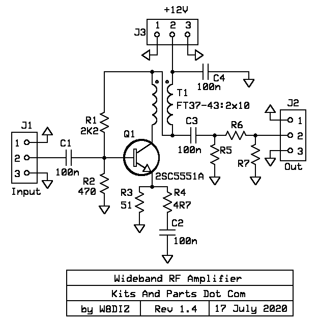
Specs:
22+ dBm power gain from 2-30 MHz
50 ohm input and 50 ohm output.
100 milliwatt maximum output.
Instructions:
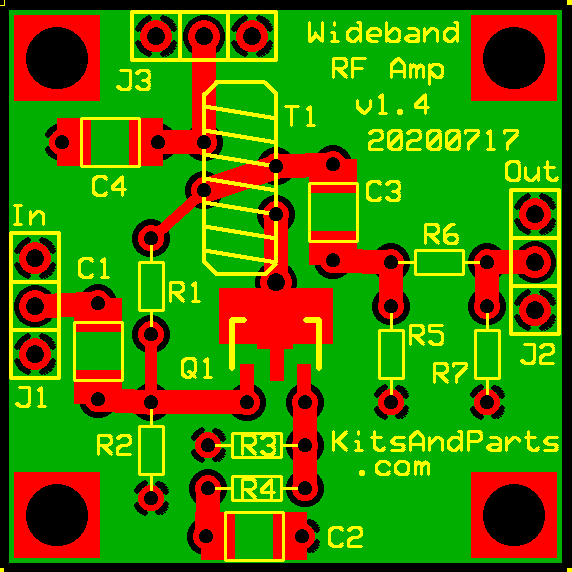
1. Align the SMD 2SC5551A RF Transistor onto Q1 pad in the center of the PCB.
Using a temperature controlled solder pencil, solder without overheating.
2. Align the four 100n SMD capacitors on the PCB and solder.
3. Install resistors R1, R2, R3 and R4 on the PCB and solder.
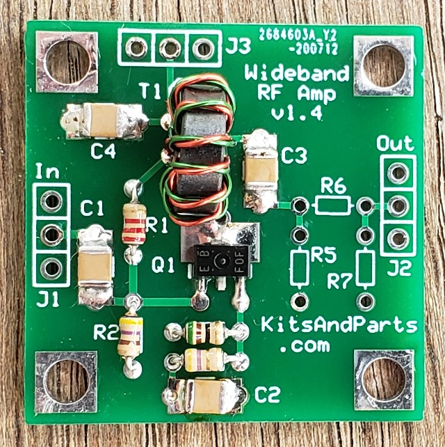
4. Install Toroids Transformer T1
Twist the Red & Green wires together to about 4 twists per inch.
Wind 10 turns of the twisted wires onto the toroid.
The magnet wire is heat stripable; trim each wire end to 3/4 inches.
Prepare the toroid wires for soldering - Magnet Wire Soldering Details Here
One of each colored wires connects under the toroid and
one of each colored wires connects on teh outside of the toroid.
One color wire should connect to J3/C4 and the other color connects to Q1
You should also have 2 different color wires connecting under the toroid via a PCB trace.
5. R5,6,7 (not included) are used to attenuate the rf output. Place a jumper wire across R6.
6. Connect the RF Amplifier via J1(input), J2(output) and J3(power).