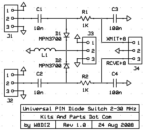
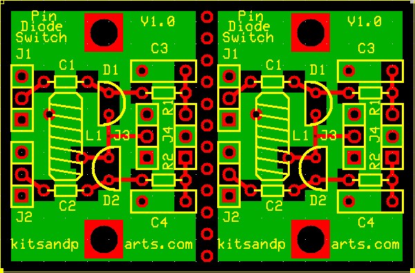
These PIN switches are designed to handle 5 milliWatts (+7dBm) or less


Nothing special about this kit which includes one
PCB holding 2 independent PIN Diode Switches.
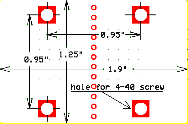
This PCB may be broken for logistic circuit placement.
When installing the PIN diodes, note the flat edge.
Common input/output is at J3 which is at DC ground.
J4 control voltage should be between 6 and 12 VDC.
BUILDING INSTRUCTIONS:
Errors: C3/4 may be 68n or 100n.
INSTALL RESISTORS:
| R1 | 18 | Brown-Black-Red-Gold | ________ |
| R2 | 18 | Brown-Black-Red-Gold | ________ |
L1____Cut the 26 ga magnet wire in half. You should have about two (2) each, eight (8) inch pieces.
Wind 12 turns tight thru L1. Cut any excess lead length so that only one (1) inch remains. Strip all of insulation from the wire pigtails to the body of T1. This wire is NOT heat strip-able. Tin the wires.
Toroid Winding Details Here
Install L1 and solder into the circuit board.
C1____Install and solder 10nF cap
C2____Install and solder 10nF cap
C3____Install and solder 68nF/100nF cap
C4____Install and solder 68nF/100nF cap
D1____Install and solder MPN3700 PIN Diode. Note polarity.
D2____Install and solder MPN3700 PIN Diode. Note polarity.
Install any headers you may have now.