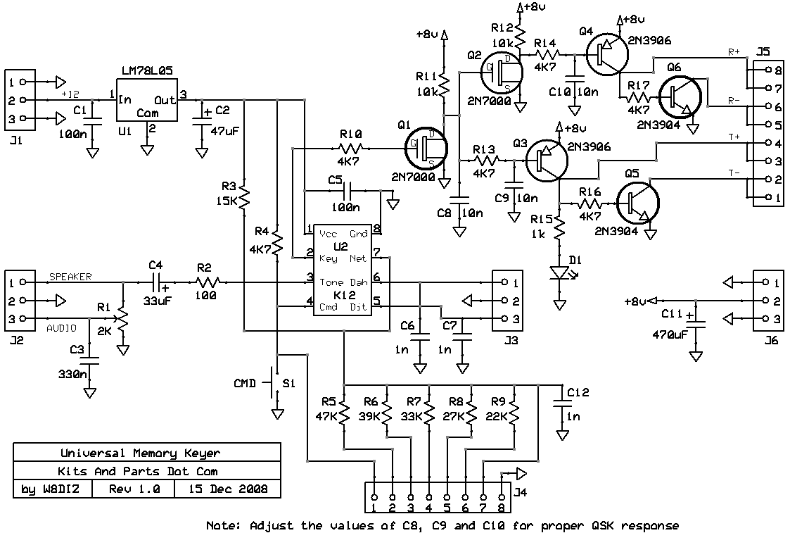
Click here For details about the K12 keyer chip


Building Instructions:
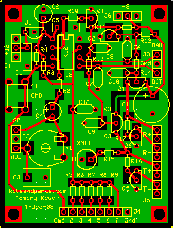
1. Inventory all Parts
2. Install all 1/8 Watt Resistors.
Note: Bend the resistor leads a sharp 90 degrees from the body
____R1: 2K ohm pot
____R2: 100 Brown-Black-Brown-Gold
____R3: 15K Brown-Green-Orange-Gold
____R4,10,13,14,16,17: 4K7 Yellow-Violet-Red-Gold
____R5: 47K Yellow-Violet-Orange-Gold
____R6: 39K Orange-White-Orange-Gold
____R7: 33K Orange-Orange-Orange-Gold
____R8: 27K Red-Violet-Orange-Gold
____R9: 22K Red-Red-Orange-Gold
____R11,12: 10K Brown-Black-Orange-Gold
____R15: 1K Brown-Black-Red-Gold
3. Install all capacitors.
____C1,5: 100n blue labeled 104
____C2: 47u - note the polarity
____C3: 330n yellow
____C4: 33u - note the polarity
____C6,7,12: 1n - labeled 102
____C8,9,10: 10n disks labeled 103
____C11: 470u - INSTALL LATER
4. Install all semiconductors.
____Q3,4: 2N3906 - note the flat edge of the transistor body
____Q5,6: 2N3904 - note the flat edge of the transistor body
____Q1,2: 2N7000 - note the flat edge of the MosFet body
____D1 Red or Green LED - note the flat edge of the LED body
____U1 78L05 - note the flat edge of the voltage regulator
____U2 K12 memory keyer socket - install with notch toward top of the PCB
____U2 K12 memory keyer chip - insert the K12 chip PIN-1 toward top of PCB
____S1: momentary switch - mounted so it will easily fit on the PCB
____C11: 470u - note the polarity
5. Testing.
Connect a speaker to pins 1 & 2 of J2
Connect +8V to J6 and +8V or +12V to J1
Momentarily press pushbutton S1; you should hear "MT" in code.
Short circuit pins 1 & 2 of J3; you should hear a string of DAHs.
Short circuit pins 2 & 3 of J3; you should hear a string of DITs.
Note that the LED will only light when transmitting / keying.
The Keyer is now finished.