The Frequency Counter Development Kit Version-1 is fully functional (once built), however,
the internal firmware will not display your call sign, but will display:
line1: "QQ FC V.1 URCALL" - (URCALL can be custom programmed upon request)
line2: "nn,nnn.nnn Khz " - (where nn,nnn.nnn is the Frequnecy)
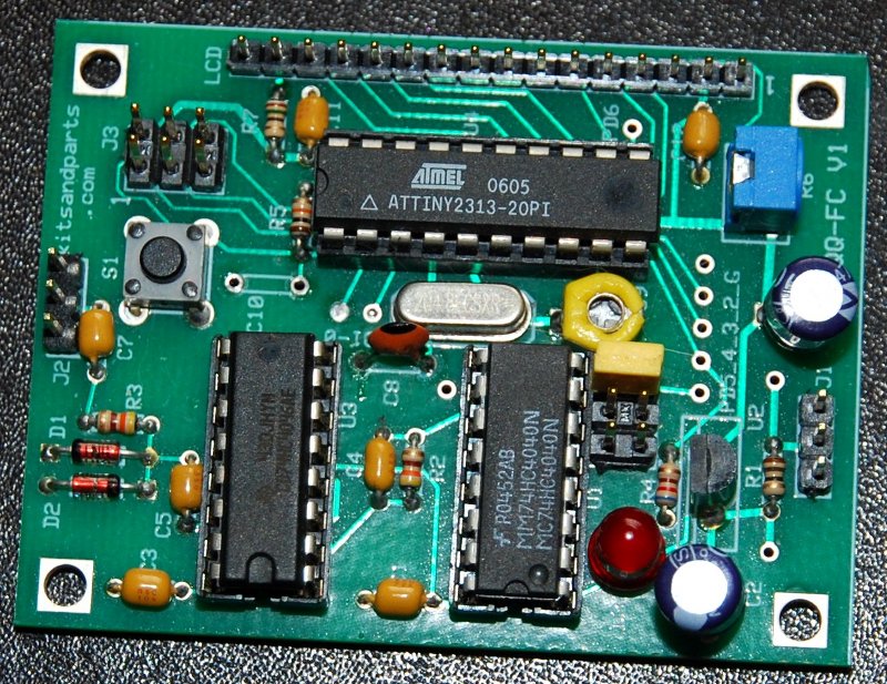
This Frequency Counter project is fully documented in the qrparci.org QRP Quarterly magazine in four consecutive issues starting with the Fall 2009 issue. The documented project starts with the installation of Linux (Mint Version) on a PC and installing the required tools on the Linux PC to draw the schematic, design the Printed Circuit Boards and write the assembler code for the freq counter, including all steps required for the reader to duplicate the Freq Counter project from concept to production. You may also follow the project on a Microsoft Windows platform; most instructions in the articles will apply to Windows, but here we are emphasizing the Linux platform for development (it's free). Below is the final result.
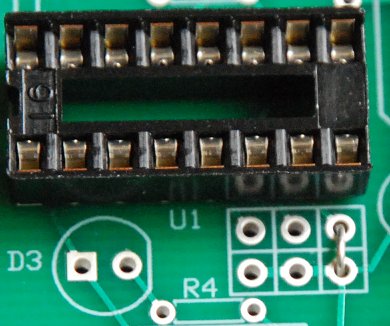
1. Solder the three (3) pre-inserted IC sockets.
2. Install all Resistors.
Note: Bend the resistor leads a sharp 90 degrees from the body
____R1: 10 Brown-Black-Black-Gold
____R2:430 Yellow-Orange-Brown-Gold
____R3:430 Yellow-Orange-Brown-Gold
____R4:620 Blue-Red-Brown-Gold
____R5:10K Brown-Black-Orange-Gold
____R6:10K Blue trimmer pot
Resistor R7 value depends upon the type of LCD LED backlight. R7 is not installed if your LCD has no LED backlight.
LCDs are available from Mouser.com or Kitsandparts.com
green backlight (10mA @ 3.3V) - $13
For a GREEN backlight, R7 is a 100 ohm resistor.
____R7: 15 Brown-Green-Black-Gold
____R7:100 Brown-Green-Brown-Gold
3. Install one jumper wire to set the prescaler to DIVIDE BY FOUR (4).
____Jumper. Install a jumper wire using a discarded resistor clipped lead per the picture. Solder.
4. Install all capacitors.
Bend the 100n capacitor leads a sharp 90 degrees from the body
____C1 100n
____C2 47u
____C3 100n
____C4 150p
____C5 100n
____C6 47u
____C7 100n
____C8 22p
____C9 40p Yellow Trimmer. Install in proper orientation with flat side toward X1
____C10 not installed
____C11 100n
____C12 100n
5. Crystal X1.
____Install the 20.48 Crystal. Leave a very small space (1/16 inch) under the crystal to prevent shorts.
6. Install all Diodes.
____D1 1N4148. Install in proper orientation with flat band toward the outer edge of the PCB.
____D2 1N4148. Install in proper orientation with flat band toward U3.
____D3 Install Red LED Diode in proper orientation with flat side toward the center of the PCB.
7. Install the Reset Switch.
____S1 Orient the push button switch for easy insertion into the PCB.
8. Install the 7805 or 78L05 Voltage Regulator.
If you are using an LCD with a high current LED backlight then you must use the LM7805 TO-220 regulator.
You may use the smaller LM78L05 TO-92 regulator if you use the green LED backlight LCD or no backlight LCD.
____U2 Orient 7805 with the TAB side towards the Red LED or the 78L05 with the FLAT side toward the Red LED.
9. Install the 6-pin Program Header.
____J1 not included
____J2 not included
____J3 used to connect to an AVRISP Programmer to modify the Freq Counter Firmware
Now is a good time to test the Voltage Regulator on the board. Apply power (9-14 VDC) via J1 and measure 5 VDC between pins 10 and 20 of socket U4. If you do not measure 5 VDC +/- 0.1 Volts, fix the problem before proceeding.
10. LCD Connection. There are many options to connect the LCD. For the LCD to function, you need to connect pins 1 thru 14 on the PCB to 1-14 on the LCD.
You can connect the LCD using your own cable. Supplied with the kit is one 14 pin male header and one 14 pin Female socket. If you are going to connect the LCD directly to the PCB, install the female 14 pin socket on the PCB and the 14 pin male header on the bottom of the LCD. If the LCD has 16 pins, make sure to install the socket using pins 1-14.
Pins 15 and 16 on the LCD connection are for LCDs that have an LED backlight.
11. Install the 16-pin ICs. Use precautions when handlimng the ICs to prevent Static Electricity damage.
____U1 MC74HC4040N - Insert the IC per the above picture. CAUTION: Note the ICs orientation.
____U3 CD74HC4046AE - Insert the IC per the above picture. CAUTION: Note the ICs orientation.
12. Install the 20-pin ATtiny2313-20PU IC.
There are two (2) 2313 chips included with the Freq Counter Dev Kit. One has a white nail-polish mark near PIN-1.
The white marked IC is used for assembly code testing per the QRP-ARCI QQ project referenced top of this page.
Inserting this IC will cause the red LED to link ON for one second and OFF for one second.
____U4 ATtiny2313-20PU - Insert the IC (without the nail-polish mark) per the above picture. CAUTION: Note the ICs orientation.
At this point, the Frequency Counter is complete.
Power (9-14 VDC) is applied to J1, Pin-2 is + and Pins 1:3 are ground.
RF input is at J2, with Pin-2 being the signal input and Pins 1:3 are ground.
Input amplitude should be a minimum of 50 to 100 mVolts P-P for proper operation.
Overvoltage protection is provided by D1 and D2; max input is 12 volts P-P.
The pre-programmed GATE TIME is 1/4 second and the DISPLAY RESOLUTION is 8 Hz
For more information about the "Development" aspects of this Frequency Counter Project,
check out the qrparci.org QRP Quarterly magazine starting with the Fall 2009 issue.