INSTRUCTIONS FOR BUILDING THE AVR-DEV Kit.
updated 01/29/04 11:00 AM

The AVR-DEV kit includes the following:
  1. Double sided plated thru PCB with AD9835 DDS
  2. Plastic bag with parts and wire
  3. Telephone KeyPad
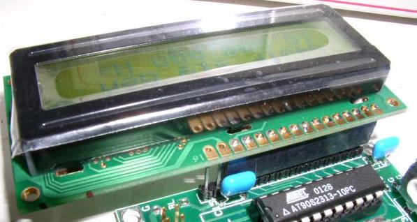
  4. Backlit 16x2 LCD
  5. Rotary Encoder
  6. Schematic

We will build the AVR-DEV in this order:
  0. Review instructions. Inspect PCB and parts.
  1. Install resistors
  2. Install tactile switches
  3. Install LEDs
  4. Install sockets and headers
  5. Install capacitors
  6. Install Pot and Xtal
  7. Wind and install all toroids.
  8. Install remaining parts


Ready...set...begin!

INVENTORY all the parts against the parts list.
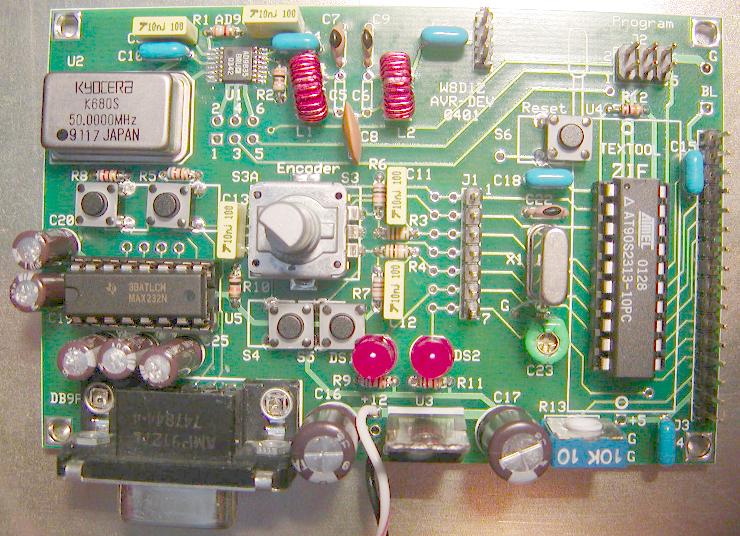
All parts are referenced on the PCB with the
RF Output connector on top of the PCB.


-------------------------------------------------------
Install all resistors. Solder and clip leads.
NOTE: All resistors are 1/8W
____ R2  ORANGE-BLACK-BROWN
____ R5  BLUE-RED-BROWN
____ R8  BLUE-RED-BROWN
____ R9  BLUE-RED-BROWN
____ R11 BLUE-RED-BROWN
____ R1  ORANGE-WHITE-RED
____ R3  BROWN-BLACK-ORANGE
____ R4  BROWN-BLACK-ORANGE
____ R6  BROWN-BLACK-ORANGE
____ R7  BROWN-BLACK-ORANGE
____ R10 BROWN-BLACK-ORANGE
____ R12 BROWN-BLACK-ORANGE

Install tactile switches.
Break off 2 of the 4 pins on the tactile swithes. See Picture.
Straighten the 2 remaining pins with needle nose pliers.
Mount the switches flat on the PCB.


NOTE: If you install a ZIF socket for U4,
then mount S6 with the body to the left.
____ S1 Tactile Switch, body to the left
____ S2 Tactile Switch, body to the left
____ S4 Tactile Switch, body to the right
____ S5 Tactile Switch, body to the right
____ S6 Tactile Switch, body to the right

Install two LEDs 1/4 inch above the PCB
Observe polarity when installing the LEDs
Long lead goes into square hole.
The bottom of DS1 should be just above switch S5
____ DS1 Red LED
____ DS2 Red LED

Install both DIP sockets
Mount with socket notch per the PCB layout
____ U4 20 pin DIP socket - notch is toward the top
____ U5 16 pin DIP socket - notch is to the left

Install all four headers.
____ J1 1x7 pin header
____ J2 2x3 pin header
____ J3 1x16 pin header
____ J4 1x3 pin header

Install all capacitors
NOTE: C5 and C6 are not installed.
____ C7  33p
____ C9  33p
____ C22 33p
____ C8  68p
____ C23 30p green trimmer
NOTE: Pre-adjust the trimmer so that the 2 little
dimples on the inside of the trimmer both point
to the left.
____ C1  10n
____ C3  10n
____ C11 10n
____ C12 10n
____ C13 10n
Straighten the leads on the 100n caps with
needle nose pliers and mount flush on the PCB.
____ C2  100n
____ C4  100n
____ C10 100n
____ C14 100n
____ C15 100n
____ C18 100n
Observe polarity with electrolytic capacitors.
PLUS goes into the square holes.
____ C19 10uF
____ C20 10uF
____ C21 10uF
____ C24 10uF
____ C25 10uF
____ C16 220uF
____ C17 220uF

Install the 10k pot
____ R13 10k pot (blue)

Install the XTAL.
Push the XTAL pins into it's holes and tilt about
20 degrees and solder. Now straighten the XTAL.
This keeps the XTAL body from touching other circuits
____ X1  10.24 MHz XTAL
Solder a cut resistor lead from "G" to the XTAL body.
Do not overheat the XTAL body. See picture.

Install the 50 MHz XTAL Ref Osc
____ U2 50 MHz - Match package outline to the PCB

____ Cut 2 pieces of 12" wires
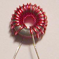
Wind both toroids EXACTLY per this picture.

____ L1 T30-2 22 Turns (12" of #27)
____ L2 T30-2 22 Turns (12" of #27)

Install the 5 volt regulator
Metal tab is towards the center of the PCB
____ U3 7805

Install DB9 connector
____ DB9F

NOTE: You may wish to mount the encoder external to the PCB.
Install the rotary encoder.
Mount the rotary encoder slightly above the PCB board
using cut leads from a 2M7 1/2 Watts resistor as a spacer.
This will prevent a potential shorting of the metal case to
some of the PCB signal lines.
____ S3/S3A Encoder
____ Remove the spacer leads

Install 2 wires to supply power to the PCB
____ Solder the purple wire to the +12 connecton
____ Solder the black wire to the G connection
     below the +12 wire near the edge of the PCB

TESTING!
The +5 volts can be measured in the lower right corner of the PCB.
While measuring the +5 volt supply on the PCB, connect 7 volts to the
power wires. The regulated voltage should be between 4.9 and 5.1 volts.
If it is out of range, STOP and fix the problem.

Install the Atmel AVR AT90S2313 processor.
Bend the pins perpendicular to the body of the IC
CAUTION: Observe polarity. IC notch, PIN#1 to top of PCB
____ Insert U4 into its socket.

Optionally insert the MAX232 chip, U5
CAUTION: Observe polarity. IC notch, PIN#1 to left of PCB
Do not get confused by the dot vs. the notch.
It is recommended that you do NOT insert this IC until
the software is ready to accept it.
____ Insert U4 into its socket when the software is ready.
Note: Some of the pins on U5 could conflict with S1 and S2


NEED HELP?
Email me ... w8diz1 at fpqrp.com


 NOTE: If you install a ZIF socket for U4,
then mount S6 with the body to the left.
____ S1 Tactile Switch, body to the left
____ S2 Tactile Switch, body to the left
____ S4 Tactile Switch, body to the right
____ S5 Tactile Switch, body to the right
____ S6 Tactile Switch, body to the right
Install two LEDs 1/4 inch above the PCB
Observe polarity when installing the LEDs
Long lead goes into square hole.
The bottom of DS1 should be just above switch S5
____ DS1 Red LED
____ DS2 Red LED
Install both DIP sockets
Mount with socket notch per the PCB layout
____ U4 20 pin DIP socket - notch is toward the top
____ U5 16 pin DIP socket - notch is to the left
Install all four headers.
____ J1 1x7 pin header
____ J2 2x3 pin header
____ J3 1x16 pin header
____ J4 1x3 pin header
Install all capacitors
NOTE: C5 and C6 are not installed.
____ C7 33p
____ C9 33p
____ C22 33p
____ C8 68p
____ C23 30p green trimmer
NOTE: Pre-adjust the trimmer so that the 2 little
dimples on the inside of the trimmer both point
to the left.
____ C1 10n
____ C3 10n
____ C11 10n
____ C12 10n
____ C13 10n
Straighten the leads on the 100n caps with
needle nose pliers and mount flush on the PCB.
____ C2 100n
____ C4 100n
____ C10 100n
____ C14 100n
____ C15 100n
____ C18 100n
Observe polarity with electrolytic capacitors.
PLUS goes into the square holes.
____ C19 10uF
____ C20 10uF
____ C21 10uF
____ C24 10uF
____ C25 10uF
____ C16 220uF
____ C17 220uF
Install the 10k pot
____ R13 10k pot (blue)
Install the XTAL.
Push the XTAL pins into it's holes and tilt about
20 degrees and solder. Now straighten the XTAL.
This keeps the XTAL body from touching other circuits
____ X1 10.24 MHz XTAL
Solder a cut resistor lead from "G" to the XTAL body.
Do not overheat the XTAL body. See picture.
Install the 50 MHz XTAL Ref Osc
____ U2 50 MHz - Match package outline to the PCB
____ Cut 2 pieces of 12" wires
Wind both toroids EXACTLY per this picture.
 ____ L1 T30-2 22 Turns (12" of #27)
____ L2 T30-2 22 Turns (12" of #27)
Install the 5 volt regulator
Metal tab is towards the center of the PCB
____ U3 7805
Install DB9 connector
____ DB9F
NOTE: You may wish to mount the encoder external to the PCB.
Install the rotary encoder.
Mount the rotary encoder slightly above the PCB board
using cut leads from a 2M7 1/2 Watts resistor as a spacer.
This will prevent a potential shorting of the metal case to
some of the PCB signal lines.
____ S3/S3A Encoder
____ Remove the spacer leads
Install 2 wires to supply power to the PCB
____ Solder the purple wire to the +12 connecton
____ Solder the black wire to the G connection
below the +12 wire near the edge of the PCB
TESTING!
The +5 volts can be measured in the lower right corner of the PCB.
While measuring the +5 volt supply on the PCB, connect 7 volts to the
power wires. The regulated voltage should be between 4.9 and 5.1 volts.
If it is out of range, STOP and fix the problem.
Install the Atmel AVR AT90S2313 processor.
Bend the pins perpendicular to the body of the IC
CAUTION: Observe polarity. IC notch, PIN#1 to top of PCB
____ Insert U4 into its socket.
Optionally insert the MAX232 chip, U5
CAUTION: Observe polarity. IC notch, PIN#1 to left of PCB
Do not get confused by the dot vs. the notch.
It is recommended that you do NOT insert this IC until
the software is ready to accept it.
____ Insert U4 into its socket when the software is ready.
Note: Some of the pins on U5 could conflict with S1 and S2
NEED HELP?
Email me ... w8diz1 at fpqrp.com

