Available Now
This kit consisting of a Beat Frequency Oscillator/Mixer and Audio Amplifier that can be used
as a Direct Conversion Receiver or as a Post IF 2nd Mixer Module with Audio Amplifier.
Circuit includes Audio derived Mixer AGC, Mute and Sidetone Input.
This kit comes in two (2) parts:
A Printer Circuit Board and all the "common" parts to build the module (base kit),
plus one selected sub-kit defined as follows:
1. Build a Direct Conversion Receiver with a user supplied DDS for tuning (parts included with base kit)
2. Build a Direct Conversion Receiver with VCXO tuning (user supplied crystal; specify band)
3. Build a Direct Conversion receiver with VFO tuning (specify band)
4. Build a 2nd Mixer / Audio Amp for a user designed SuperHet Receiver (user supplied BFO crystal; specify band)
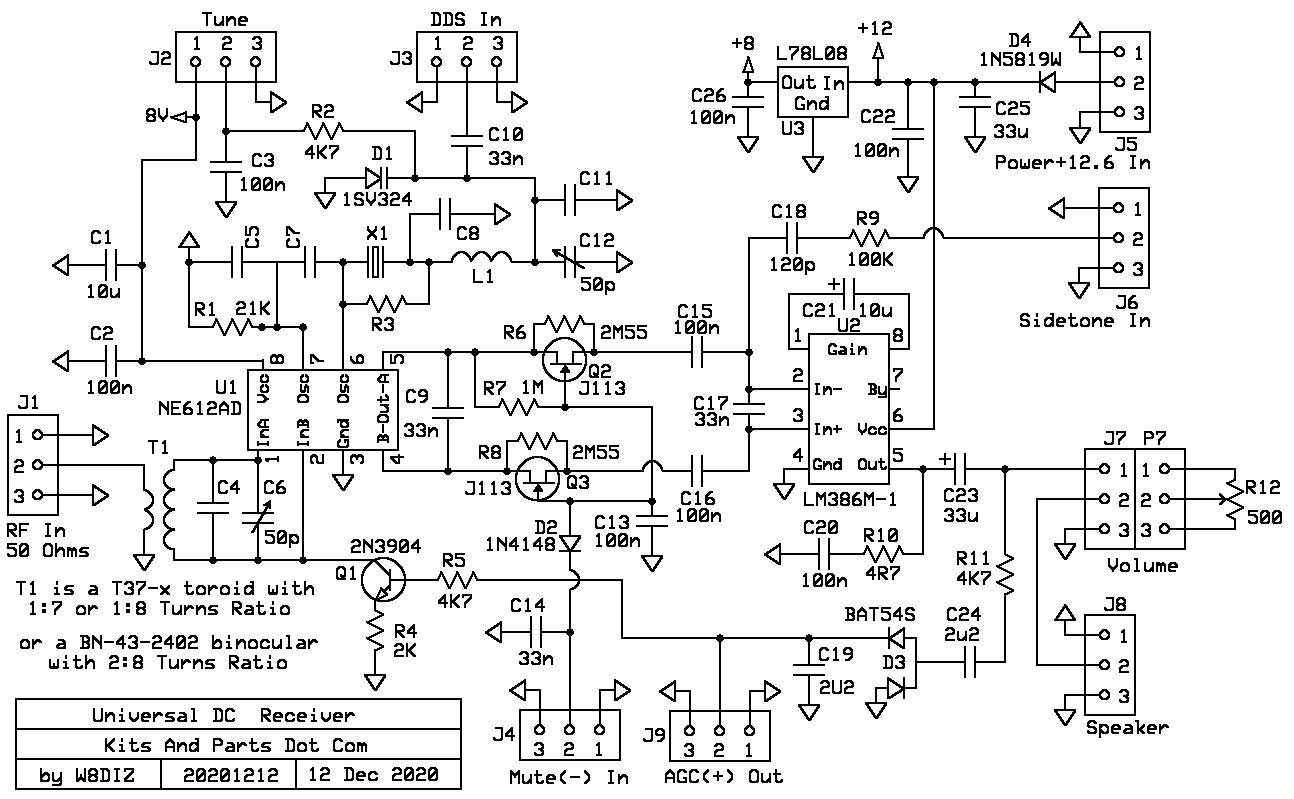
Production Schematic: ExpressPCB Schematic Source File
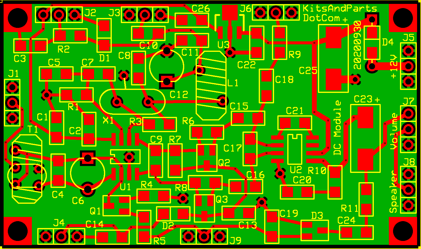
Production PCB: ExpressPCB Board Layout Source File
This kit does NOT include:
_____ Power Connector and Power Switch
_____ PCB Enclosure
_____ Hookup Wire
For Solder Pencil Soldering, this kit recommends:
_____ Good Quality 45 Degree Diagonal Tweezers.
_____ HAKKO FX-888D Temperature Controlled Solder Pencil.
_____ CircuitWorks CW 3220 Liquid Flux.
_____ Kester Solder 63/37 .028
For Hot Air Soldering, this kit recommends:
_____ Hot Air Gun Model 858D (or better).
Search http://ebay.com for item # 274463047101
_____ CircuitWorks CW 3220 Liquid Flux.
Search http://ebay.com for item # 202373307435
_____ Kester Solder 63/37 .020 (0,5 mm)
_____ Mechanic Solder Paste XGZ40 63/37 Paste/Flux 183 Deg C, IPX3, 35g
Search http://ebay.com for item # 223803694552
Building Instructions:
1. DO NOT remove any parts from the kit until instructed to do so.
2. Some helpful SMT Info / Links
Surface-Mount Soldering Notes by W8BH, Bruce Hall

Youtube Link About Desoldering And Flux

Youtube Link About Capacitors

Youtube Link General SMT Tutorial

Youtube Link Hot Air SMT
3. Try to limit the handling of the SMT parts; they have a tendancy to disappear.
If using a hot air gun, you may wish to organize the parts installation into sections.
4. Install these first.
_____ D4 - 1N5819W labeled as S4 - qty 1 (Schottky Reverse Polarity Protection Diode)
_____ U1 - NE612AD Mixer - qty 1
_____ U2 - LM386-M1 Audio Amp - qty 1
5. Install the unmarked capacitors.
_____ Cut the 8.5 x 11 piece of paper that is holding the unmarked parts into parts strips.
_____ C1,21 - 10uF - qty 2 - install and solder.
_____ C2,3,13,15,16,20,22,26 - 100n 20% - qty 8 - install and solder.
_____ C4 - ???pF - qty 1 - frequency specific part
Only install C4 if using a tuned input at T1.
C4 value is determined by the input frequency.
0 pF if greater than 9 MHz
100 pF for 7 MHz if T1 = T37-2[4:30] (Included with kit)
180 pF for 3.5 MHz if T1 = T37-1[4:31]
220 pF for 1.8 MHz if T1 = T37-61[4:31]
Do not install C5,7 if using a DDS, else install both.
_____ C5,7 - 150p (included with kit) - qty 2 - install and solder.
C5 & C7 values depend on the oscillator frequency; 150 pF is a tradeoff (included)
use 220pF for freq below 7 MHz and 100pF for freq above 10 MHz
C8 value is determined based on DCM function
For VCXO operation, C8 is a 4p7 cap
For DDS operation, C8 (your part) may be used as part of a PI filter network
_____ C8 - ???pF - qty 1 - install and solder.
Do not install C10 unless the DCM is configured for DDS
_____ C9,10,14,17 - 33n - qty 4 - install and solder - Only install C10 if using a DDS
C11 value is determined based on DCM function
For DDS operation, C11 may be used as part of a PI filter network
For VFO operation, C11 may be used as part of a tune network
_____ C11 - ???pF (user supplied) - qty 1 - install and solder.
_____ C12 - 50 pF trimmer may optionally be installed later
_____ C18 - 120p - qty 1 - install and solder.
_____ C19,24 - 2u2 - qty 2 - install and solder.
_____ C23,25 - are installed later
Do not install D1 if using a DDS or a Fixed Frequency BFO Crystal
Note the Cathode Line marking for diode D1
The Cathode connects with R2 (pointing down towards C7)
The Cathode Line marking for diode D1
If you can't see the cathode line, compare with a 1N4148 using ohm-meter
_____ D1 varactor - qty 1 - install and solder - this is the smalled part in the SMD parts bag, not labeled
6. Install all SMD 1206 resistors.
_____ R1 - 21K1Ω - qty 1 - labeled 2102 Only install R1 if X1 is installed and does not oscillate.
_____ R2 - 4K7Ω - qty 1 - labeled 472 - Only install R2 if using TUNE Pot at J2
_____ R5,11 - 4K7Ω - qty 2 - labeled 472
Only install R3 if using a DDS.
R3 value should be sized so the DDS signal at pin-6 of U1 is 650-750 mV P-P
_____ R3 - ???Ω - qty 0 - labeled as ??? install and solder.
_____ R4 - 2KΩ - qty 1 - labeled as 202
_____ R6,8 - 2M55Ω - qty 1 - labeled as 2554 (values establish "natural sidetone" volume)
_____ R7 - 1MΩ - qty 1 - labeled as 1004 (AGC Delay Cap)
_____ R9 - 100KΩ - qty 1 - labeled as 104 (value establishes synthetic sidetone volume from xmtr)
_____ R10 - 4R7Ω - qty 1 - labeled as 4R7
7. Install all SMD diodes.
Note the Cathode Line marking for diode D2
_____ D2 - 1N4148 - qty 1 - labeled as T4
_____ D3 - BAT54S (dual diode) - qty 1 - labeled as L44 (note orientation on PCB)
8. Install the voltage regulator and remaining SMD transistors.
_____ U3 - L78L08 - qty 1 labeled as 78L08
_____ Q1 - 2N3904 - qty 1 labeled as 1AM (AGC Amplifier)
_____ Q2,3 - J113 - qty 2 labeled as 6S (Mute Switches)
_____ C23,25 - 33uF - qty 2 labeled as 336
_____ C6 - 50pF - qty 1 brown trimmer caps (only install with tuned input configuration)
_____ C12 - 50pF - qty 1 brown trimmer caps (only install with fixed frequency BFO Crystal)
9. Install L1 toroid
If using a DDS, L1 is optionally a part of a PI filter - your design
_____ L1 - T37-2 25 turns or more when X1 is greater than 6 MHz
_____ L1 - FT37-61 12 turns or more when X1 is less than 6 MHz
10. Install Transformer T1 (Balun or Toroid)
_____ T1 Ferrite Balun BN-43-2402 - for use with CRYSTAL FILTER front end
Cut 10" of #34 red wire and 4" of #30 red wire.
Wind 8 turns of #34 red wire on an BN-43-2402 black ferrite binocular core.
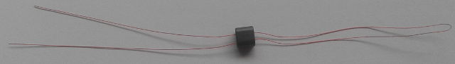


Trim the red wires of T1 to one inch each.
Wind 2 turns of #30 red wire on the BN-43-2402 black ferrite binocular.
Trim the #30 wires of T1 to one half inch each.
Strip & Tin the insulation on all 4 wires to the base of the binocular.
The #34 wire leads for the 8 Turn winding go to the two pads toward the bottom of the PCB connect to C4
The #30 wire leads go to the two pads in the middle which connect to GND and J1
Install T1 into the PCB, pull the leads tight using needle nose pliers, solder and trim.
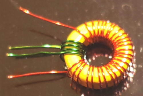
_____ T1 Powdered Iron Toroid or Ferrite Toroid for TUNED front end
Remove a FT37-61, T37-2 or T37-6 toroid from the Bag
Create a transformer with a 1:7 or 1:8 turns ratio (your design)
Install T1 onto the PCB
NOTE: Wound toroid may be red, yellow or black; yellow T37-6 core shown.
11. Install the 3-Pin headers onto the PCB where needed
12. Install all external controls to the PCB
Production Parts List:
Parts List:
Part-ID             Value       Quantity
C1,21               10uF        2 not labeled
C2,3,13,15,16,20,22,26 100n     8 not labeled
C4                  RFinTuneCap see documentation
C5,7                BFO Caps    see documentation
C6                  50pF        1 brown trimmer see documentation
C8                              see documentation
C9,10,14,17         33n         4 not labeled
C11                             see documentation
C12                 50pF        1 brown trimmer see documentation
C18                 120p        1 not labeled
C19,24              2u2         2 not labeled
C23,25              33uF        2 labeled as 336

L1                  VFO/VCXO/DDS see documentation

R1                  21K         1 labeled as 2102
R2,5,11             4K7         3 labeled as 472
R3                  DDS limiter see documentation
R4                  2K          1 labeled as 202
R6,8                2M55        2 labeled as 2554
R7                  1M          1 labeled as 1004
R9                  100K        1 labeled as 104
R10                 4R7         1 labeled as 4R7

D1                  1SV324      1 Varactor not labeled see documentation
D2                  1N4148      1 labeled as T4
D3                  BAT54S      1 (dual diode) labeled as L44
D4                  1N5817      1 1N5819 labeled as S4

L1                  T37-7 & T37-2 & FT37-61 fixed BFO tune or VFO tune

Q1                  2N3904      1 labeled as 1AM
Q2,3                J113        2 labeled as 6S

T1                  Toroid or Balun see documentation
T1                  BN-43-2402  1 used for balanced untuned input
T1                  T37-6 & T37-2 & FT37-61 balanced tuned RF input filter

U1                  NE612AD     1 labeled as N612A
U2                  LM386       1 labeled as LM386-M-1
U3                  L78L08      1 labeled as 78L08

X1                  BFO Crystal - user supplied - order separately

J1 RF Input Connection
J2 Panel Mount 100KΩ Tune Control (user supplied)
J3 DDS Connection
J4 External Mute (-) In
J5 Power +10.5 to +12.6 VDC
J6 Side Tone In from Transmitter
J7 Panel Mount 500Ω Main Volume Control
J8 Output 3.5 mm Speaker Stereo Connector
J9 AGC(+) Output

Six (6) 3-Pin male headers
Three (3) 3-Pin female-to-female connection cables (suit your needs - cut into six pieces?)
R12 1K Volume Control connect to P7
3.5mm Stereo Jack for Speaker
28 ga red magnet wire 20 inches (3F4)
30 ga red magnet wire 24 inches (3F5)
34 ga red magnet wire 10 inches (3F2)