UNDER CONSTRUCTION - prototype build
Production Version Available ~ Late February, 2021
Functions & Specs:
50Ω Input & 50Ω Output
~66 dB gain or better
3.0 x 1.4 inches PCB footprint
This kit does NOT include:
_____ Power Connector and Power Switch
_____ PCB Enclosure
_____ Hookup Wire
For Solder Pencil Soldering, this kit recommends:
_____ Good Quality 45 Degree Diagonal Tweezers.
_____ HAKKO FX-888D Temperature Controlled Solder Pencil.
_____ CircuitWorks CW 3220 Liquid Flux.
_____ Kester Solder 63/37 .028 - use for other parts.
For Hot Air Soldering, this kit recommends:
_____ Hot Air Gun Model 858D (or better).
Search http://ebay.com for item # 274463047101
_____ CircuitWorks CW 3220 Liquid Flux.
Search http://ebay.com for item # 202373307435
_____ Kester Solder 63/37 .020 (0,5 mm) - use for SMDs.
_____ Mechanic Solder Paste XGZ40 63/37 Paste/Flux 183 Deg C, IPX3, 35g
Search http://ebay.com for item # 223803694552
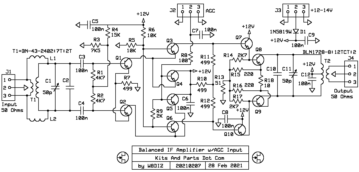
Prototype Schematic: ExpressPCB Schematic Source File
 |
 |
 |
Prototype PCB: ExpressPCB Board Layout Source File
Building Instructions:
1. DO NOT remove any parts from the kit until instructed to do so.
Keep the lone single black toroid in the SMD bag segregated from the other black toroids.
2. Some helpful SMT Info / Links
Surface-Mount Soldering Notes by W8BH, Bruce Hall
Youtube Link About Desoldering And Flux
Youtube Link About Capacitors
Youtube Link General SMT Tutorial
Youtube Link Hot Air SMT
3. Try to limit the handling of the SMT parts; they have a tendancy to disappear.
If using a hot air gun, you may wish to organize the parts installation into sections.
4. Install the unmarked SMD capacitors next.
_____ C1,3,4,5,6,7,8,9,10,11,12,13,14 - 100n 20% - qty 13 - install and solder.
C2A is not needed for 9 MHz and is not included.
5. Install all SMD 1206 resistors.
_____ R1,5,14 - 220Ω - labeled as 221
_____ R2,6 - 100KΩ - labeled as 104
_____ R3,7,12,13 - 100Ω - labeled as 101
_____ R4 - 22Ω - labeled as 220
_____ R8 - 51Ω - labeled as 510
_____ R9 - 10KΩ - labeled as 103
_____ R10,17 - 21KΩ - labeled as 2102
_____ R11,15 - 2KΩ - labeled as 202
_____ R16,22 - 1KΩ - labeled as 102
_____ R18,21 - 35K7Ω - labeled as 3572
_____ R19,20 - 4K7Ω - labeled as 472
6. Install all SMD diodes.
Note the Cathode Line marking for diode D3
_____ D1 - BAV99 (SOT-23) Dual Signal Diode - labeled as KJE-50
_____ D2 - 5V6 Zener (SOT-23) - labeled as 8GM
_____ D3 - 1N5819W Schottky Diode - labeled as S4
7. Install the voltage regulator and remaining SMD transistors.
_____ Q1,3,5,6,7,9 - 2N3904 (SOT-23) - labeled as 1AM
_____ Q8 - 2N3906 (SOT-23) - labeled as 3N
_____ Q2,4 - J310 (SOT-23) - labeled as 6T
8. Install Trimmer Cap.
_____ C2 - 50pF brown trimmer cap
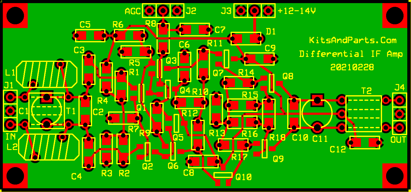
9. Install Suppressor Beads.
Insert 1 inch resistor leads through the FB-43-101 ferrite beads
Bend the resistor leads as shown...
_____ Z1,2 - Install beads at Z1 & Z2
10. (optional) Install all five, 3-Pin headers on top of the PCB
_____ J1,2,3,4,5 - 3-Pin Headers
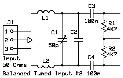
11. Install L1 and possibly C2A (Input Matching Network - transforms 50Ω to 2700Ω)
These instructions are for a 9 MHz IF
Other IFs require different L/C values for L1 & C2A
To calculate the network values for other frequencies
go to http://toroids.info/FT37-67.php
_____ Cut 12 inches of the red #27 magnets wire
_____ Retrieve the FT37-67 ferrite toroid from the SMD parts bag
_____ Wind 18 turns evenly spaced on the toroid
_____ Cut the wire ends to a length of 1/2 inch; Strip the insulation and Tin with Solder
_____ Install at L1 location on the PCB
_____ C2A is not required for an IF of 9 MHz
12. Install Toroid Inductors L2 & L3
_____ Cut two pieces of #27 red magnet wire to 9 inches each
_____ Wind 12 turns on both FT37-43 black toroids
_____ Cut the wire ends to a length of 1/2 inch; Strip the insulation and Tin with Solder
_____ Install L2 & L3 onto the PCB
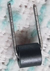
13. Install Toroid Transformer T1
_____ Cut one piece of #27 red magnet wire to 9 inches each
_____ Wind 12 turns on an FT37-43 black toroid
_____ Wind 5 turns of green magnet wire on the toroid
_____ Cut the wire ends to a length of 1/2 inch; Strip the insulation and Tin with Solder
_____ Install T1 onto the PCB with the green wires in the middle-center of T1
Parts List:
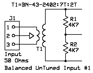
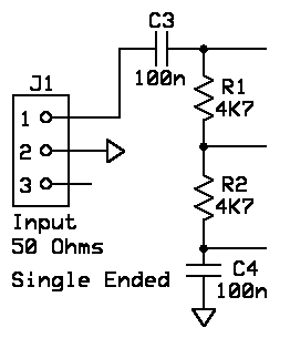
Part-ID         Value       Quantity

C1              50 pF Trimmer Cap - not included
C2              part of C1, L1, L2 circuit for balanced tuned input - not included
C3,4,5,6,7,8,9  unmarked 100n bypass/coupling caps - not labeled
C10             100 pF optionally used for tuned output with C11
C11             50 pF brown trimmer used with T2 (observe polarity marking on PCB)

D1              1N5819W Schottky Diode labeled S4

L1,2            part of circuit for balanced tuned input - not included

Q1,3,5,6,7,9    2N3904 labeled as 1AM
Q8              2N3906 labeled as 3N
Q2,4            J310 labeled as 6T

R1,2,3          4K7 labeled as 472
R4,5,6          10K labeled as 103
R7,10           499 labeled as 4990
R11,12          750 labeled as 7501
R8              100 labeled as 101
R9              2K labeled as 202
R13             51 labeled as 510
R14,17          2K7 labeled as 272
R15,16          220 labeled as 221
R18             4R7 labeled as 4R7

T1              BN-43-2402 [2 turns : 7 turns] binocular
T2              BLN1728-8 [12 Turns CT : 2 turns] binocular
-->