PCB ONLY - Available Now
Over the last twenty (20) years or more, we have all noticed that common through hole electronic parts are becoming more scarce
or are no longer available. They are no longer being manufactured because of lack of high volume demand.
For those of us that like to play "electronics" we must either buy up all the old through hole parts on the surplus market
or become familiar with (read not afraid of) surface mounted electronic parts.
I have created this SMT Training Kit as a Training Tool for SMT/SMD construction, mostly for my own training :)
To build this kit, I am relying on the skills that we have learned over the years doing standard through hole soldering.
Instead of pushing resistor leads through holes, soldering and clipping,
we are going to solder/build a kit using 1206 size SMT devices using tweezers with a fine tip solder pencil.
The Kit may also be built using a Hot Air Gun and Solder Paste, in addition to Soldering Pencil.
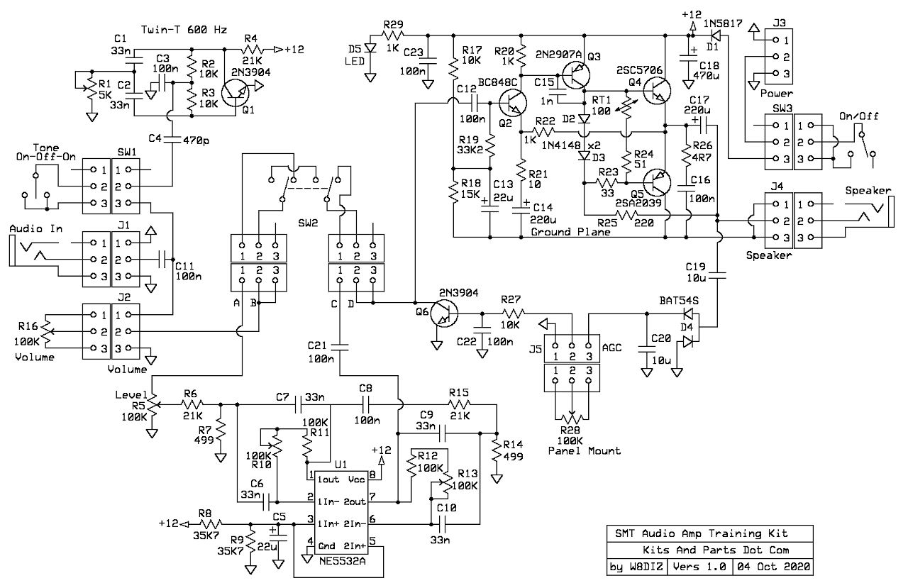
The kit we are building is an audio utility tool consisting of a high quality 3 Watt RMS Audio Amplifier with adjustable AGC,
an adjustable audio band pass filter and a CW spotting/tone generator.
Functions & Specs:
3 Watts RMS High Quality Audio Amp with adjustable AGC
Twin-T Sine Wave Audio Oscillator (400-1000 Hz Adjustable)
Active Audio Band Pass Filter (500-740 Hz Adjustable)
This kit includes the following:
_____ One sheet of paper with "blue taped" unmarked surface mount Capacitors and One Thermistor
_____ One small plastic bag with the small surface mount devices (SMDs) and one 1N5817 Schottky Diode
_____ One larger plastic bag with PCB (2.0" x 4.0").
_____ One larger plastic bag with one electrolytic and the list of below parts: four Tantalum capacitors.
_____ Two (2) Yellow 220uF Tantalum capacitors
_____ Two (2) Yellow 22uF Tantalum capacitors
_____ Panel Mount DPDT BandPassFilter In/Out switch
_____ Panel Mount SPST Spot/Tone Pushbutton Switch
_____ Three 100KΩ Trim Pots to adjust the BandWidth Filter
_____ One 5KΩ Trim Pot to adjust Twin-T Oscillator
_____ Nine (9) 3-Pin male headers
_____ Panel Mount 100KΩ Main Volume Control with knob
_____ Panel Mount 100KΩ AGC Control with knob
This kit does NOT include:
_____ Power Connector and Power Switch
_____ PCB Enclosure
_____ Hookup Wire
_____ Offboard connectors
_____ Knobs for potentiometers
For Solder Pencil Soldering, this kit recommends:
_____ Good Quality 45 Degree Diagonal Tweezers.
_____ HAKKO FX-888D Temperature Controlled Solder Pencil.
_____ CircuitWorks CW 3220 Liquid Flux.
_____ Kester Solder 63/37 .028 - use for other parts.
For Hot Air Soldering, this kit recommends:
_____ Hot Air Gun Model 858D (or better).
Search http://ebay.com for item # 274463047101
_____ CircuitWorks CW 3220 Liquid Flux.
Search http://ebay.com for item # 202373307435
_____ Kester Solder 63/37 .020 (0,5 mm) - use for SMDs.
_____ Mechanic Solder Paste XGZ40 63/37 Paste/Flux 183 Deg C, IPX3, 35g
Search http://ebay.com for item # 223803694552
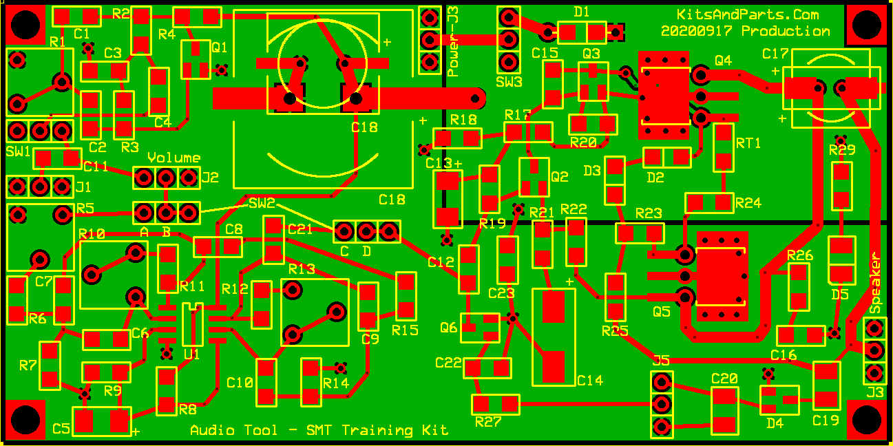
Schematic: ExpressPCB Schematic Source File
PCB: ExpressPCB Board Layout Source File
Building Instructions:
1. DO NOT remove any parts from the kit until instructed to do so.
2. Here are some helpful SMT Links:
Surface-Mount Soldering Notes by W8BH, Bruce Hall

Youtube Link About Desoldering And Flux

Youtube Link About Capacitors

Youtube Link General SMT Tutorial

Link About This Audio Amp Circuit
3. Try to limit the handling of the SMT parts; they have a tendancy to disappear.
4. Install the first.
_____ D1 - 1N5817 - qty 1 - Thru-Hole Part
_____ U1 - NE5532 Op Amp - qty 1
_____ Fill with solder, 12 small horizontal vias/holes around the top & bottom of Q4 & Q5
_____ The 3 holes to the left and right of Q4 & Q5 respectively should not be filled
5. Install the unmarked capacitors and Thermistor next.
_____ Cut the 8.5x11 piece of paper that is holding the unmarked parts into parts strips.
_____ Remove the unmarked Thermistor RT1 from the bottom strip.
_____ Install RT1 at RT1 next to Q4's Base.
_____ C1,2,6,7,9,10 - 33n - qty 6 - install and solder.
_____ C3 - 100n 10% - qty 1 - install and solder.
_____ C4 - 470p - qty 1 - install and solder.
_____ C8,11,12,16,21,22,23 100n 20% - qty 7 - install and solder.
_____ C15 - 1n - qty 1 - install and solder.
_____ C19,20 - 10uF - qty 2 - install and solder.
6. Install all SMD 1206 resistors.
_____ R2,3,17,27 - 10KΩ - qty 4 - labeled as 103
_____ R4,6,15 - 21KΩ - qty 3 - labeled as 2102
_____ R7,14 - 499Ω SMD - qty 2 - labeled as 4990
_____ R8,9 - 35K7Ω - qty 2 - labeled as 3572
_____ R11,12 - 100KΩ - qty 2 - labeled as 104
_____ R18 - 15KΩ - qty 1 - labeled as 1502 (blue)
_____ R19 - 33K2Ω - qty 1 - labeled as 3322 (blue)
Note that R29/D5 is an independent circuit to indicate power status.
R29 (1KΩ default) sets the brightness of the LED
You may wish to install R29 optional 4K7Ω to reduce brightness
or not even install R29/D5 to save on current consuption
_____ R20,22,29 - 1KΩ - qty 3 - labeled as 102
_____ R21 - 10Ω - qty 1 - labeled as 100
_____ R23 - 33R2Ω - qty 1 - labeled 33R2
_____ R24 - 51Ω - qty 1 labeled as 510
_____ R25 - 220Ω - qty 1 - labeled as 221
_____ R26 - 4R7Ω - qty 1 - labeled as 4R7
7. Install all SMD diodes.
Note the Cathode Line marking for diodes D2 & D3
The Cathode for D2 is on the left and D3 points down
_____ D2,3 - 1N4148 - qty 2 - labeled as T4
_____ D4 - BAT54S (dual diode) - qty 1 - labeled as L44
_____ D5 - LED - qty 1 - note polarity mark/notch
8. Install all remaining SMD transistors.
_____ Q1,6 - 2N3904 - qty 2 - labeled as 1AM
_____ Q2 - BC848C - qty 1 - labeled as 1L
_____ Q3 - 2N2907A - qty 1 - labeled as 2F
_____ Q4 - 2SC5706 - qty 1 (form leads just like the 2SA2039)
_____ Q5 - 2SA2039 - qty 1
9. Install all remaining SMD parts.
_____ C5,13 - 22uF - qty 2 Tantalum Line on part is (+)
_____ C14,17 - 220uF - qty 2 Tantalum Line on part is (+)
_____ C18 - 470uF - qty 1
_____ R1 - 5KΩ Blue Pot - qty 1 - Twin-T Freq Adjust
_____ R5 - 100KΩ Yellow Pot - qty 1 - Band Pass Filter Audio Volume Match Level
_____ R10,13 - 100KΩ Yellow Pot - qty 2 - Band Pass Filter Peak Audio Adjust
10. Install the 3-Pin headers onto the PCB
_____ Install Headers at SW1, J1, J2
_____ Install Headers at SW2 - there are two (2) headers for SW2
_____ Install the J5 and AGC Level Header.
Note that there are two (2) headers labeled J3 on the PCB
The Speaker Header is also labeled J3 but should be J4; Install the J3/Speaker Header
_____ Install the Speaker Header
_____ If you are using "your own" On/Off Power Switch, Install Header at SW3
_____ If you are not using an On/Off Power Switch, run a jumper wire between the upper holes of the SW3 header holes
_____ If you are using a "your own" Power Connector, Install Header at Power/J3
11. Install all external controls to the PCB
_____ Connect a 100KΩ pot to J5 for AGC control
_____ Connect a 100KΩ pot to J2 for Volume control
_____ Connect the Red SPTT Switch to SW1 to enable/disable the Twin-T OScillator
_____ Connect the Blue DPDT Switch to both SW2 headers to enable/disable the BPF
_____ Connect an 8Ω or 4Ω Speaker to the J3/Speaker Header
_____ Adjust all four (4) trim pots to center position.
_____ Connect a user supplied power on/off switch to SW3 header, if installed
_____ Verify the polarity of capacitors C18 and C17
_____ Wear some protective eyewear/glasses in case a capacitor goes BOOM!
_____ When ready for the smoke test, connect 12-14 VDC to the header labeled "Power-J3"
Center Pin is Positive; Outer pins are Ground.
Uncleaned PCB using Blue 100K Trim Pots, not Yellow which are in the kits.
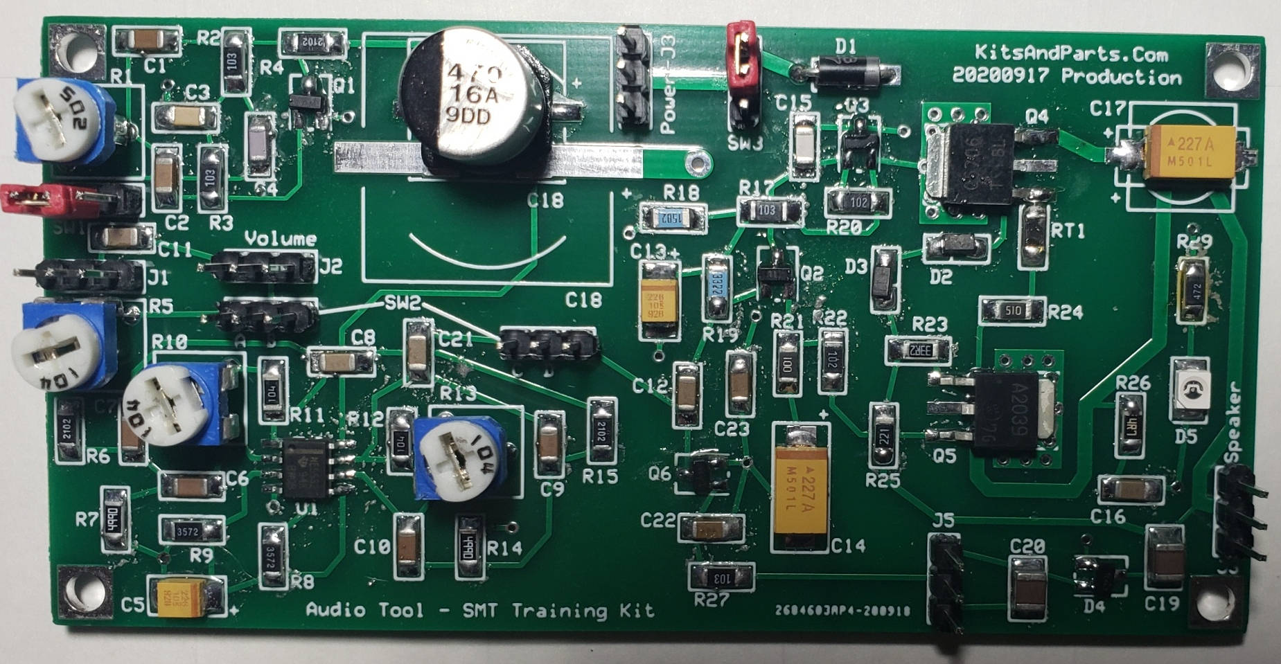
Click Picture To Enlarge (in a new window)
12. Twin-T Oscillator and Band Pass Filter Alignment
_____ Complete all items in Section 11 above.
_____ Enable the Twin-T Oscillator feed using SW1.
_____ Enable the Band Pass Filter using SW2.
_____ Verify that all four (4) Pots on the PCB are in their center position
_____ Turn up the volume control connected to J2; you should hear an audio tone from the speaker
_____ Adjust R1 to 600 Hz or your desired listening freq.
_____ Measure from the speaker connection using a Freq Counter or Scope
_____ Adjust R10 & R13 for maximum signal after you adjust R1 to your preferred listening frequency.
_____ Adjust R5 to balance audio levels between BPF ON vs BPF OFF.
Parts List:
Part-ID           Value       Quantity
C1,2,6,7,9,10     33n         6 not  labeled
C3                100n 10%    1 not  labeled
C4                470p        1 not  labeled
C5,13             22uF        2 labeled as 226
C8,11,12,16,21,22,23 100n 20% 7 not  labeled
C14,17            220uF       1 labeled as 227
C15               1n 5%       1 not  labeled
C18               470uF       1 labeled as 470 16A
C19,20            10uF        2 not  labeled

R1                5K Pot      1 labeled as 502
R2,3,17,27        10K         4 labeled as 103
R4,6,15           21K         3 labeled as 2102
R5,10,13          100K Pot    3 labeled as 104
R7,14             499         2 labeled as 4990
R8,9              35K7        2 labeled as 3572
R11,12            100K        2 labeled as 104
R16 (Panel Mount) 100K Volume 1 (J2)
R18               15K         1 labeled as 1502
R19               33K2        1 labeled as 3322
R20,22,29         1K          3 labeled as 102
R21               10          1 labeled as 100
R23               33          1 labeled as 33R2
R24               51          1 labeled as 510
R25               220         1 labeled as 221
R26               4R7         1 labeled as 4R7
R28 (Panel Mount) 100K AGC    1 (J5)
R29               4K7         1 labeled as 472 (optional LED brightness resistor)
RT1 Thermistor    100         1 not  labeled

D1                1N5817      1 (Thru-Hole Part)
D2,3              1N4148      2 labeled as T4
D4                BAT54S      1 (dual diode) labeled as L44
D5                LED         1 note polarity mark/notch is cathode

Q1,6              2N3904      2 labeled as 1AM
Q2                BC848C      1 labeled as 1L
Q3                2N2907A     1 labeled as 2F
Q4                2SC5706     1
Q5                2SA2039     1

U1                NE5532      1 Dual Low Noise Op Amp

SW1 Panel Mount SPST pushbutton switch for Spot/Tone
SW2 Panel Mount DPDT Band Pass Filter On/Off (In/Out)
J3 SW3 Panel Mount SPST Power Switch On/Off (not included)
J1 Audio Input Connector (not included)
J4 Output Connector (not included)
Panel Mount 100KΩ Main Volume Control
Panel Mount 100KΩ AGC Control
Nine (9) 3-Pin male headers