OUT OF STOCK
|
This document describes the building of the 5Watter Organic Transceiver Kit Last Updated Tue, 12 Dec 2023 19:58:59 -0500 Always check the Addendum Section for updates |
|
Build this 5Watter QRP VCXO Transceiver for $49.00
The 5Watter is a high quality inexpensive transceiver designed for the QRP enthusiast
Guaranteed 5 Watts output using 12 VDC (5W using 14 VDC on 17M)
Designed for home and portable operation.
Small Size PCB, only 3.5 inches (89 mm) square.
Full QSK, dual conversion design with great selectivity
Very low noise measured at -137 dBm MDS
The 5W10 VCXO covers 28,035 to 28,062 KHz (experimental)
The 5W17 VCXO covers 18,068 to 18,097 KHz
The 5W20 VCXO covers 14,001 to 14,066 KHz
The 5W30 VCXO covers 10,100 to 10,130 KHz
The 5W40 VCXO covers 7,002 to 7,046 KHz
Includes multifunction keyer chip with "natural" sidetone
Full Size Schematic (17,20,30,40m) opens new window Full Size Schematic (10m) Experimental opens new window
PCB Layout (17,20,30,40m) opens new window PCB Layout (10,12,15m) Experimental opens new window
Development History opens new window K7QO’s 5W 20m Assembly Guide opens new window
Building Instructions for 5W20 14.001-14.066
DO NOT REMOVE ANY PARTS FROM THE PLASTIC BAGS UNTIL INSTRUCTED TO DO SO
Be careful when you inventory the parts; they are small and easy to lose.
There are five (5) main plastic bags that hold all the parts for the 5Watter Kit.
Keep all parts in their respective bags; do not mix them up.
There are size 37 black toroids in the bags that look identical but are NOT.
The two black toroids in the bag with the green 100n capacitors are FT37-43.
The shiny black toroids in the 17 meter band bag are T37-10.
Dull looking black toroids in other band bags are FT37-61.
The 40 meter band bag contains a smaller bag with two FT37-67 black toroids.
There are also Red Diodes that look identical but are NOT.
Bag#1, the one with the Printed Circuit Board (PCB) contains two (2) 1N5711 red diodes.
Bag#1 also contains straight and right angle headers, raw pins, housings and cables.
Use these any way you wish to connect the PCB to your volume, tune and gain controls etc.
Parts in this document are installed in a sequence that facilitates ease of installation.
If you wish to take a more educational approach to building this kit, you might check out www.k7qo.com/5w.pdf
Thanks to Chuck Adam, K7QO for providing the pdf document (Over 200 pages...WOW!)
If you are missing any parts, contact me immediately. I will ship the parts the same day.
If you find extra parts in the kit, check the Addendum else throw them in your junk box.
Parts List for 5W20 14.001-14.066 (opens in new window)
Each 5Watter is provided with a Serial Number, which is attached to the bag holding the PCB.
Attach the label to the rear of your 5Watter enclosure or wherever suitable.
The Serial Number may later be used for tracking 5Watter QSO contests.
This kit requires the following items to complete the kit:
No. 22 or 24 gauge hook-up wire to connect the PCB to the controls and enclosure.
Rosin Solder 60/40 (OK) or 63/37 (Best) and a fine tip solder pencil.
Tool for adjusting trimmer capacitors: suggest search for GC-8608
Optional freq counter: Search ebay for PLJ-0802, Manual for the Frequency Counter
Optional keyer speed adjust potentiometer: Recommend 10K linear.
Optional power on/off switch.
Optional case: Suggested 5Watter Cases
1. The PCB in Bag#1 has the 8 pin DIP socket and Keyer IC inserted in the PCB.
____ : Remove the Keyer IC from the socket and place in a safe place; solder the socket to the PCB.
2. Install all Surface Mount ICs (SMD); note polarity when installing.
All SMD ICs are located in bag within the large bag that holds the PCB
A picture is worth a thousand words...also search Google "how to solder SMD ICs"
2.1 Install U4, the LM386 Audio Amp IC
____U4 LM386-M-1 Audio Amp IC (from the bag with the PCB)
2.2 Install U1,2,3, the NE612AD Mixer ICs
____U1,2,3 NE612AD Mixer ICs (from the bag with the PCB)
2.3 Install D9,13, the 1N5711 Diodes
____D9,13 1N5711 Diodes (from the bag with the PCB)
3. Install most of the parts from the bag with the green caps
Mark this Bag as #3 for future reference.
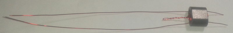
3.1 Install transformer T6
From the bag with the 24 green capacitors, remove the black binocular and the #34 red wire.
____T6: Wind 8 turns of #34 red wire on an BN-43-2402 black ferrite binocular.
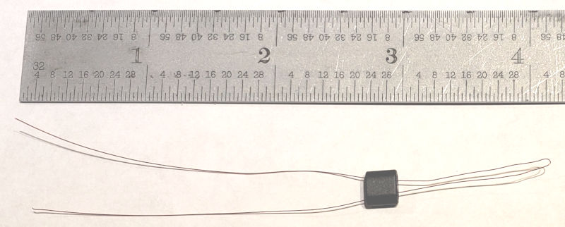
Bend the wire in half and insert the wire ends into both binocular holes. This is one turn.
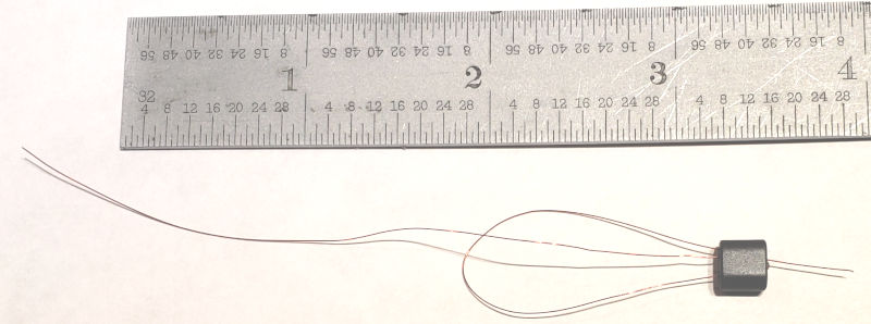
Pull the wire end through the binocular and wind 7 more full turns throught the binocular
The binocular end with the wires coming out will show 8 loops between the holes.
The other end of the binocular will show 7 loops between the holes.
Trim the red wires of T6 to one inch each.
From the bag with the band number, remove 3 inches of the thin #30 red wire.
Wind 2 turns of #30 red wire on the BN-43-2402 black ferrite binocular.
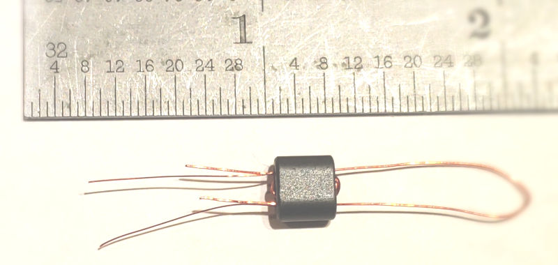
Trim the #30 wires of T6 to one half inch each.
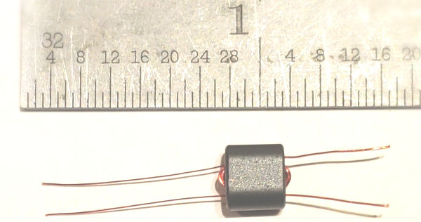
Strip & Tin the insulation on all 4 wires to the base of the binocular.
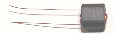
The #34 wire leads for the 8 Turn winding go to the two pads closest to the IC, Pins 1 and 2.
The #30 wire leads go to the two pads farthest away from the IC or toward the bottom of the PCB.
Install T6 into the PCB, pull the leads tight using needle nose pliers, solder and trim.
3.2 Install all 24 pieces 100n (0.1uF) green capacitors
____C6,7,9,10,11,13,21,22,23,25,28,29,32,C39,42,44,45,46,48,53,54,55,56,58
3.3 Install D5, the smaller red diode labeled 1N5240B; bend leads sharply 90 deg.
____D5 1N5240B 10 Volt Zener, Red, Smaller
3.4 Install D3,4 the larger red diodes labeled 1N4751; bend leads sharply 90 deg.
____D3,4 1N4751 30 Volt Zener, Red, Larger
3.5 Install D10,11 the small blue diodes labeled NPC-127; bend leads sharply 90 deg.
____D10,11 NPC-127 Blue 5.6 Volt Zener
The remaining 3 toroids, (2)FT37-43 and (1)FT50-75 will be installed later.
4. Install all 1/8 Watt Resistors.
You may need a magnifying device to verify the resistor color codes.
Bend the resistor leads a sharp 90 degrees from the body of the resistors.
R20, the volume control will be connected later.
Save 5 cut resistor leads to ground the crystal cases later.
____R1,2,6 51R GreenBrownBlackGold
____R3 10R BrownBlackBlackGold
____R4 5K6 GreenBlueRedGold
____R5,13,17,32,33 470R YellowPurpleBrownGold
____R7 120R BrownRedBrownGold
____R8,18,19,31,34,35 4K7 YellowPurpleRedGold
____R9 1K0 BrownBlackRedGold
____R10 2K Trim Pot located in Bag#2 with other Pots
____R11,23 (not used, not included)
____R12,16,29 10K BrownBlackOrangeGold
____R14 3K3 OrangeOrangeRedGold
____R15 20K RedBlackOrangeGold 5% or RedBlackBlackRedBrown 1%
____R20,21,22 2K2 RedRedRedGold
____R24,28 1M BrownBlackGreenGold
____R25,26 2M2 RedRedGreenGold or 4M7 YellowPurpleGreenGold
____R27 4R7 YellowPurpleGoldGold
____R30 (Only install to reduce AGC gain) 4K7 YellowPurpleRedGold
____R36 (Only install if NOT using a speed pot) 470R YellowPurpleBrownGold
5. Install all remaining Diodes - observe polarity.
Bend all leads a sharp 90 degrees from the body of the diodes.
____D1,2,7,8: 1N4148 red glass diodes
____D6: MV209 varactor - leave 1/8 inch (3 mm) space between the PCB and diode body
____D12: 1N5817 black diode
6. Install all Male and Female headers.
If you plan on using Male/Female connectors to attach the PCB to the controls etc then
install the Male headers at this time; located in the large plastic bag with the PCB
Using a proper sharp tool, cut the 40 piece vertical header into smaller 3 pin headers.
Install 10 3-pin male headers on the top of the PCB at J1 through J10.
If you do not plan on using a CW Speed Pot, you do not need to install J10 but instead
you must install R36, a 470 ohm resistor near J10.
CAUTION: If you do not plan on using the AUX J3 connection, do not install the J3 header because
it is way too easy to connect power to J3 instead of J1 and toast the 5Watter
____J1-J9 Header 3-Pin Make, install on top of PCB with short pin ends inserted into PCB; then solder.
____J10 Header 3-Pin Make, install on top of PCB with short pin ends inserted into PCB; then solder
...or...
____R36 470R YellowPurpleBrownGold
____Install the two (2) Female 3-pin headers at Q1a & Q1b; these are sockets for the RF Final Transistors
7. Install transformers T1 & T2.
7.1 Install transformer T1
There are two (2) binocular cores in a 3x5 inch plastic bag marked with the Band Number.
Remove the larger binocular from the bag.
Cut 7 inches of #26 Green wire.
____Wind 4 full turns #26 Green wire through T1. Trim to 3/4 inches.
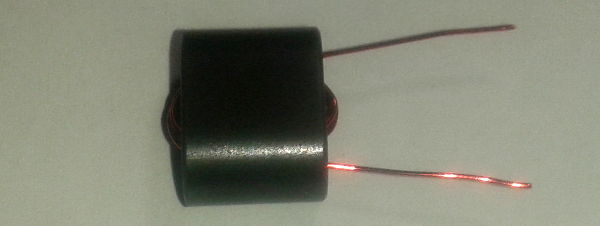
Cut 8 inches of #26 Green wire. Fold in half and insert into T1 as shown.
Leave a 3/4 inch loop; tightly twist the loop per the picture for one half inch.
____Wind 4 turns #26 Green wire through T1 center tapped at 2 turns. Trim to 3/4 inches
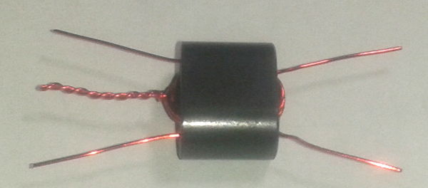
Strip and tin the wires using a hot solder pencil and solder
Align and Install T1 on the PCB into the holes per the picture. Solder and trim leads.
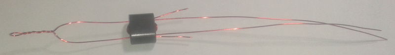
7.2 Install transformer T2
Remove the smaller binocular from the bag.
Cut 5 inches of #26 Green wire.
____Wind 4 full turns #26 Green wire through T2. Trim to 3/4 inches.
Cut 4 inches of #26 Green wire. Fold in half and insert into T2 as shown in T1.
Leave a 3/4 inch loop; tightly twist the loop per the picture for one half inch.
____Wind 2 turns #26 Green wire through T2 center tapped at 1 turn. Trim to 3/4 inches
Strip and tin the wires using a hot solder pencil and solder
Align and Install T2 on the PCB into the holes per the pictures. Solder and trim leads.
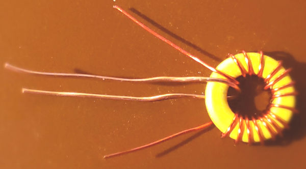
8. Install transformers T3 & T4 & T5.
8.1 Install transformers T3 & T4
Remove the two T37-6 Yellow Toroids from the Band Bag.
Cut 2 pieces of 11 inches #27 Red magnet Wire.
Wind 16 turns #27 Red wire on T3; duplicate for T4. Trim to 1 inch.
Spread the turns over 80-90 pct of the toroids
Strip and tin the wires using a hot solder pencil with solder.
Remove the two, 3 inch twisted wires from Bag #3. Unwind & Strip to bare copper & cut to 2 inches.
Wind 1 turn copper wire through T3; repeat for T4.
____Install T3 & T4 onto the PCB; #27 wire on the outside, bare copper link center under toroid.
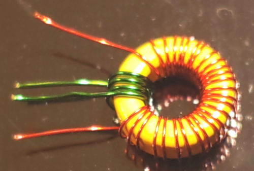
8.2 Install transformer T5
Remove a T37-6 Yellow Toroids from the Band Bag.
Cut 18 inches #30 Red magnet Wire.
Wind 28 turns #30 Red wire on T5. Trim to 3/4 inches
Remove the 4 inch Green #27 wire from Bag #3.
Wind 4 turns #27 Green wire on T5. Trim to 3/4 inches
____Install T5 onto the PCB; #30 wire on the outside, Green wire center under toroid.
9. Install all six (6) Yellow Trimmer Caps.
___C5 - ceramic Trimmer
___15,16,18,31,43 - 45p Yellow Trimmer
Observe Polarity - flat side of trimmer.
Adjust all trimmer caps to Midway Capacitance (See notes at bottom of page)
10. Install all Toroid Inductors.
10.1 Install L1, L2, L3
Remove the three T50-6 Yellow Toroids from the Band Bag.
Cut three pieces (11 inches each) of Green #26 wire
Wind 12 turns evenly spaced on one toroid only.
Wind 13 turns evenly spaced on the other two toroids.
Trim all leads to 3/4 inches; Tin the leads; Install the 12 turn toroid at L3.
____Install the 13 turn toroids at L1 & L2.
10.2 Install L4
Remove one FT37-61 dull Black Toroids from the Band Bag.
Cut 9 inches of Red #27 wire.
Wind 14 turns evenly spaced on the toroid.
____Trim all leads to 3/4 inches; Tin the leads; Install at L4.
10.3 Install L5 & L6
Remove the two black FT37-43 Black Toroids from Bag #3.
Cut 2 sets of 8 inches Green #26 wire.
Wind 10 turns evenly spaced on each toroid.
____Trim all leads to 3/4 inches; Tin the leads; Install at L5 & L6.
10.4 Install L7
Remove one T37-2 Red Toroids from the Band Bag.
Cut 18 inches of Red #30 wire.
Wind 31 turns evenly spaced on the toroid.
____Trim all leads to 3/4 inches; Tin the leads; Install at L7.
10.5 Install L8 & L9
Remove two FT37-61 dull Black Toroids from the Band Bag.
Cut 13 inches of Red #27 wire.
Wind 20 turns evenly spaced on the toroid.
____Trim all leads to 3/4 inches; Tin the leads; Install at L8 & L9.
11. Install the following Transistors, Regulators and Semiconductors.
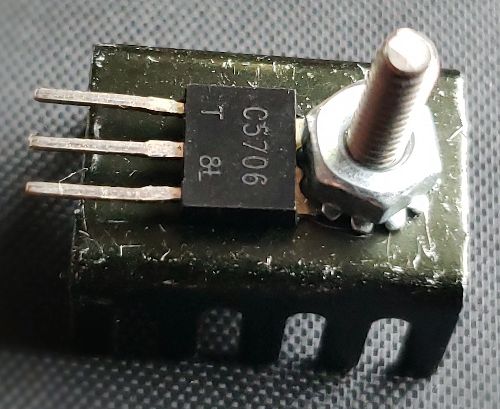
___Q2 2SC5706 Transistor with small Metal Collector Tab (Tab towards T2)
___Q3,5,6,7,8 MPSH10 TO92 (Q3 may be replaced with MPS901 for 10m)
___Q4 J310 TO92
___Q9,10 J113 TO92
___Q11 2N3906 TO92
___Q12 2N7000 TO92
___U6 78L05 TO92
___U7,8 78L08 TO92
12. Install all remaining Capacitors.
___C1,4 220p Disc from Band Bag.
___C2,3 470p Disc from Band Bag.
___C8 100p Disk labeled NPO 101J
___C12 1n Disc labeled 102 ZL
___C14,17 100p mono labeled 101 (5W10 uses 43p)
___C19,20,40,41 100p mono labeled 101 (5W17 uses 220p)
___C24 1p5 disc labeled 1.5 CL or CF
___C26,52 33p Disc labeled NPO 33J
___C27 47p mono labeled "470."
___C33,Cx 4p7 disc labeled 4.7 CL
___C34,35,36,37 680p mono labeled 681
___C38,47 10uF electrolytic
___C49,57 47uF electrolytic
___C50 33uF electrolytic
___C51,59 2u2 mono labeled 225
13. Install all Crystals.
There are 5 "IF" crystals included in the kit.
These crystals are graded for frequency and resistance.
If you find a crystal with a black dot, install it in X6.
If you find 2 crystals with black dots, install in X2 & X6.
The Filter Crystals X3,4,5 should not have a black dot.
When installing the crystals, tilt the crystals about 20 degrees while soldering
This will raise the crystal a small bit above the PCB after straightening
and will prevent trace shorts to the case of the crystal
Do not overheat the crystals.
___X1 22.1184 Mhz ECS-221-S-1X
___X2,3,4,5,6 8.064 Mhz Custom China
When soldering the crystal cases to ground, do not overheat the crystals
____Solder one resistor lead from the side of X1 to the ground hole below C28
____Solder one resistor lead across the top of crystals X3,4,5
____Solder one resistor lead from the side of X4 to the ground hole below U7
____Solder one resistor lead from the side of X2 to the ground hole below R11
____Solder one resistor lead from the side of X6 to the ground hole below C41
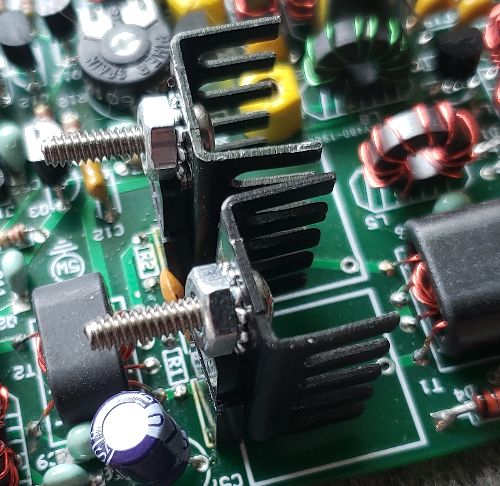
14. Install the RF Final Transistors Q1a,b
Mount two 2SC5706 transistors directly to the Aluminum Heat Sinks as shown in the picture.
Insert the Assy's into the three pin female headers as shown
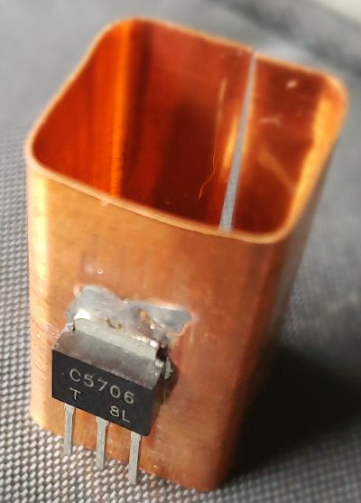
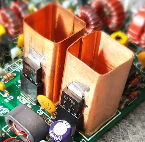
Optional custom Copper Heat Hink; solder transistors with lead ends 1/16th inch from bottom of sink
Copper is 2" x 1" x 0.012 thick, available on website as optional item.
Set solder pencil to 750 degrees; tin back of transistor tabs and then tin copper tower.
Place Copper tower on it's side; position 2SC5706; heat the copper above the tab until parts joined.
Insert the Assy's into the three pin female headers as shown
15. Connections.
Suggested 5Watter Cases
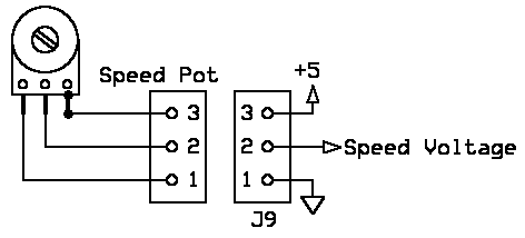
Connect a user supplied pot (10K or 100K) to the "speed pot" connector J10.
Connect the speed pot control wiper to the center hole on J10.
If you do not install a speed pot then you must install R36
Install R36, 470 ohms.
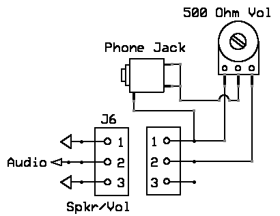
Connect the 500 ohm or 1K volume pot using any insulated wire.
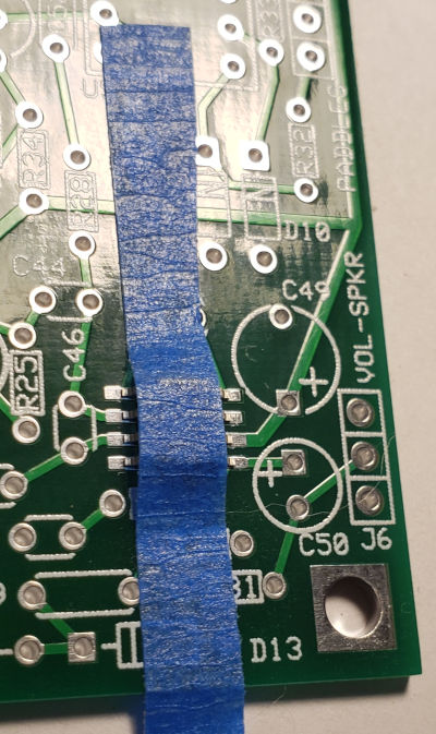
Connect the volume control high side to the center of J6 on the PCB.
Connect the volume control cold side to a ground on J6.
Connect the volume control center wiper to a 3.5 mm phono jack
Connect the 3.5 mm phono jack ground to the cold side of the volume control pot.
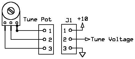
Connect the 100K pot to the "Tune" connector J8.
Connect the tune control wiper to the center hole on J8.
Connect the provided BNC connector to the "Ant" connection next to L1 on the PCB.
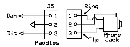
Connect paddles or a straight key to J5 via the other 3.5 mm phono connector
Connect the Push Button, one wire to the center of J4, the other wire to one of the ground connections
Before you apply power to the 5Watter, make sure your power polarity is correct
The 5Watter was designed to operate from a 12 volt Sealed Lead Acid Battery
Connect +12.6V volts (+/- 1 volt) to the holes "J1" in the upper right corner of the PCB.
16. Receiver Alignment.
The alignment of the receiver & transmitter sections of the 5Watter Transceiver centers around the
Center Frequency of the CW Band Pass Filter. All Band Pass Filter crystals were matched to within 25 Hz.
The average center frequency for the 5W20 is 8,061,700 Hz
If you like your CW tone that you hear from the speaker to be near 600 Hz, then
we want to set the BFO to 600 Hz higher that the center of the band pass filter frequency.
If you have an RF Sig Gen and a Scope, this is easy. I will assume that you do not have such equipment.
Connect any antenna to the 5Watter or a wire at least a few meters long.
Set the volume control to max and apply power to the 5Watter.
Adjust C5 and C31, back and forth for maximum noise coming from the speaker/headphones.
Also adjust C43 to set the typical pitch of the noise for a narrow bandpass audio response.
You may hear some CW signals by turning the Tune Pot.
The object here is to set C43 so that the loudest/strongest audio is at 600 Hz
17. Transmit Alignment using an Oscilloscope or a Calibrated Accurate Receiver
The band pass filter (X3,4,5) establishes the IF center frequency.
The transmit oscillator part of U1, X2, L8 & C18 should match the IF frequency +/- 100 Hz.
Find a signal in the tuning range of the transceiver. As you tune across the signal,
the loudest audio frequencies should be about 600 Hz +/- 100 Hz
Next we will adjust for maximum carrier output.
You will need an HF receiver, oscilloscope or dummy load with power meter.
If you do not have either, we will align the transmitter after we install the final transistor.
The Voltage Controlled Crystal Oscillator (Q5) and the Transmit Carrier Oscillator (U1) are mixed
to produce the 5Watter transceiver transmit frequency.
The mixer (U1) also produces other frequencies that must be rejected.
Preset the power control R10 to half way (max current draw should not exceed 800 mA)
Preset C16 and C15 at 50 percent maximum capacitance (see settings in addendum section)
C16 has broad tuning while C15 has very sharp tuning.
Preset the Tune Pot to half way or in the middle.
Place the Keyer into straight key mode
While listening to a receiver near the QRP calling frequency or watching a scope at the junction of R1/Q1a,
adjust C15 to max signal on the scope or receiver.
You should verify that the signal is the QRP frequency and not another mixer freq.
If using a receiver, you will need to hunt for the actual signal.
After finding the signal, readjust both C16 and C15 for maximum signal.
Make sure that you have aligned the filter to the correct frequency and not an alternate
frequency generated by the transmit mixer.
18. Sidetone volume setting.
The Command Sidetone Volume is fixed/set by R28, 1M & C52, 33p.
To lower the Command Sidetone volume, decrease the value of C52 or increase the value of R28
To raise the Command Sidetone volume, increase the value of C52 or decrease the value of R28
Alternate parts for R28 and C52 are not included in the kit.
The Natural Sidetone volume is set by R25 and R26 resistors near Q9 & Q10
19. Transmit Final Alignment using milliamp meter
Connect a 50 ohm dummy load to the output of the transceiver
Connect a Power Supply (12V) through amp meter
Place the keyer into straight key mode (see instructions below)
Key the transmitter and adjust R10 for exactly 775 milliamps.
If C15 & C16 were not aligned in a prior step then preset C15 and C16 to 50 pct capacitance
Ajusting C16 for maximum milliamps current. Adjust R10 to keep the current below 775 Ma.
repeat several times until you know that C15 & C16 are peaked and R10 is set for 775 Ma.
If you have a wattmeter, insert it between the dummy load and the transceiver.
It should measure very near 5 watts output.
You may also adjust R10 for 45 volts P-P on a scope.
It is recommended that you do not adjust R10 for more than 5 watt to prevent instability/overheating.
Verify that you have adjusted C15 and C16 to the band operating frequencies by monitoring using a Receiver
or Oscilloscope or other instrument capable of verifying your output frequency.
Adjust C18 so that the transmit mixer oscillator is the same frequency as the center of the BPF.
Set your keyer with sidetone OFF by issuing a CMD and sending an "A" to turn the sidetone on/off.
If it sends an "N" then there should be NO sidetone audio.
Place the keyer into straight key mode by issuing a CMD and sending an "E" or "T".
Key the transmitter and adjust C18 to produce 600 Hz audio. Use your ears...cheapest instrument around.
This completes the 5Watter Transceiver alignment.
The 5Watter Service Manual (same as 1Watters)
The 5Watter Troubleshooting (same as 1Watters)
20. The Keyer v.4 Instructions
This is a very basic Iambic-Mode-B Keyer using an ATmel AVR Microprocessor
On power-Up, the keyer defaults to 15 WPM and a sidetone of 625 Hz and annunciates "5W" [ ..... .-- ] via Int'L Morse Code.
Connecting a straight key with a Mono Plug automatically places the keyer into straight key mode.
Moving the "Speed Pot" changes the speed from 5 WPM up to 36 WPM (version 3 and higher only)
The internal timing oscillator in the Keyer Chip is an RC oscillator that runs at 9.6 MHz +/- 10 pct Factory Calibration.
Typical accuracy is +/- 5 percent; The accuracy can be impoved to +/- 2 percent if one takes the time to calibrate
the oscillator and reprogram the keyer chip. This procedure is too time consuming for 200 chips but may be OK for you.
The accuracy is typically +/- 5 pct so your sidetone may be off by +/- 5 pct and your keying WPM may also be off.
That means if you set the WPM speed to 20 WPM, you may actually have it set at 19 or 21 WPM; should not be a problem.
The keyer is placed into the "Command" mode by pressing and releasing the Cmd Button.
The keyer has the following commands available after pressing the Cmd Button:
"A" (.-) Toggles transmit sidetone audio
The sidetone mode setting is saved on power-down.
If transmit sidetone flag was set, then clear flag and announce "Y"; Y=yes, we turn on transmit sidetone audio
If transmit sidetone flag was clear, then set flag and announce "N"; N=no, we turn off transmit sidetone audio
CMD Sidetone Audio is always active when a CMD is issued.
Enable this Mode when using the "natural" transmit sidetone.
"B" (-...) Enter Beacon Mode
Hit CMD button and enter "B" to start Beacon Mode
Listen for a DIT to acknowledge ready to select message number
Enter message number...1, 2 or 3
Message repeats over and over
Hit paddles, dit or dah or straight key to turn off beacon mode
"E" (.) or "T" (-) Toggles between normal keyer and straight key mode, acknowleged by annunciating
"S" (for Straight Key Mode) in code. The keyer mode is NOT saved on power-down.
Connecting a straight key with a Mono Plug automatically places the keyer into straight key mode.
"M" (--) Enter Beacon Message(s)
Hit CMD button and enter "M" to enter message
Listen for a DIT to acknowledge ready to select message number
Enter message number...1, 2 or 3
Listen for a DIT to acknowledge ready to enter a character
Enter one character at a time, then wait for another "dit"
To enter a word space, do not enter anything in between annunciated "dits"
At the end of the message, do not forget to add empty character time.
This allows you to pause and listen between CQ calls. Recommend 25 or more word spaces.
Terminate message entry mode by send "AR" or ".-.-."
"R" (.-.) Toggles between normal and reverse paddles keys, acknowleged by annunciating "P" (for normal paddles)
or "X" (for reversed paddles) in code. The paddles (normal or reverse) are saved on power-down.
"S" (...) Set keyer speed in WPM. Speed is entered as two numerical digits.
After sending the "S" command, the keyer sends a DIT (e) as a prompt for the first speed character (0-4)
After sending the first speed number, wait for another DIT (e) prompt and send the 2nd number (0-9)
Depending upon what you enter, you will hear a "?" for ERROR or an "R" for a "Roger" acknowlegement.
Valid keyer speeds are 1 to 45 WPM (good luck trying to send/use 1 WPM)
The keyer speed setting is saved on power-down.
"F" (..-.) Sets the sidetone frequency.
After sending the "F" command, the keyer sends a DIT (e) as a prompt for the tone character (0-9)
Depending upon what you enter, you will hear a "?" for ERROR or an "R" for a "Roger" acknowlegement.
The sidetone frequency setting is saved on power-down.
The following table equates the sidetone number with the sidetone frequency:
0 = 1000 Hz
1 = 833 Hz
2 = 714 Hz
3 = 625 Hz
4 = 555 Hz
5 = 500 Hz
6 = 455 Hz
7 = 417 Hz
8 = 385 Hz
9 = 357 hz
"V" (...-) Announces the keyer version number
"X" (-..-) Puts the keyer into transmit or tune mode
Hit paddles dit or dah or straight key to turn off tune mode
Disable the keyer sidetone for the "natural" transmit sidetone.
The keyer has Deadman Insurance. In the event that the keyer issues 64 successive DITs or
64 successive DAHs, the keyer will shut down and cease to operate.
You must power down the keyer chip to restart normal operation.
To Reset the Keyer to the Default mode, hold the Cmd button active until you hear "5W"
Then immediately release the Command Button, else you will send another Command request.
Source code and hex files for the keyer are available at http://kitsandparts.com/5watters/keyer
Notes:
Variable capacitor settings:
| Maximum Capacitance | Midway Capacitance | Minimum Capacitance | |||
|---|---|---|---|---|---|
 |  |  |
If you need an alignment tool for the trimmers, look up "GC 8608" - available at newark.com and onlinecomponents.com
We recommend the purchase of the optional Universal Interconnect Kit #2. The kit includes
30 female pins, 40 male pins and 10 3-pin (1x3) header housings.
A crimping tool is available from ebay.com for creating cables.
Search Ebay for SN-28B Pin Crimping Tool
or visit http://www.ebay.com/itm/321699003334
A How-To video https://www.youtube.com/watch?v=GkbOJSvhCgU
Addendum Section:
July 10 2019 1700Z - started shipping 5Watters
July 13 2019 1700Z - some 5Watters shipped with serial numbers less than 37 may be missing the LM386M-1
July 14 2019 1700Z - Changed the order of soldering... install the SMD parts first
July 21 2019 1700Z - Q8 was missing from the Docs for SN#1-49; added Q8, an MPSH10 TO92 Transistor.
July 21 2019 1700Z - 2N3904 is a good substitute for Q8 but the BASE and EMITTER are reversed.
Feb 28 2020 1200Z - Added 10 meters version but data only...kit not available
Jul 16 2020 1200Z - changed T1 turns in instructions to match schematic & parts list
End of Addendum Section: top