Modified Hartley VFO/VCO
Freq Coverage as shown: 1930KHz - 1985 KHz
Mix with 5.067 IF for 40 meters 6.997 - 7.052 coverage
Output as shown: adjustable from 2.5 milliWatts - 13 milliWatts
Note that 5 mW = +7 dBm for RF injection in a simple diode ring mixer.
BUILDING INSTRUCTIONS:
Errors: D3 is labeled D2 on top of the PCB
D4 is labeled D3 on top of the PCB
The VFO KIT has a +9 volts marking on the PCB. It should be +10V.
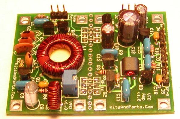
The picture below shows C17/18 as yellow but they are blue.
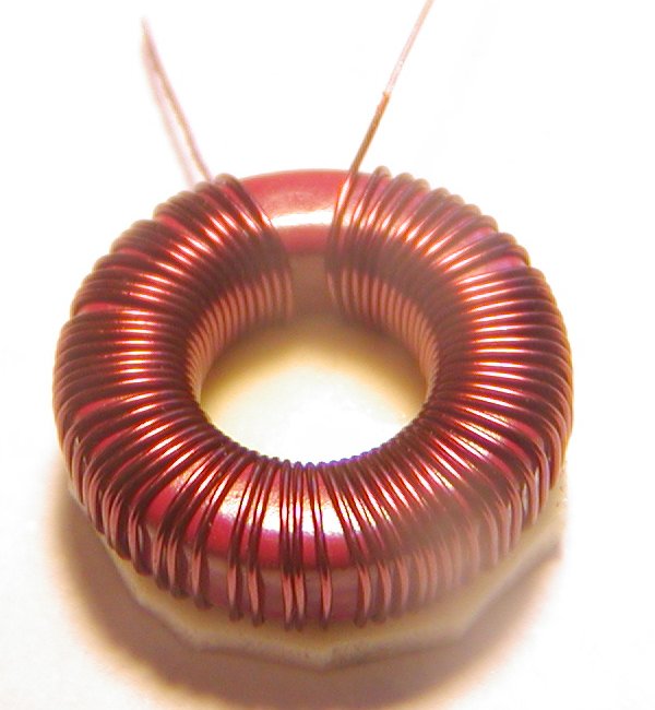
The "main" tune toroid (L1) is a T68-2 with 69 turns of #28 wire.
Some of you may suggest that this toroid should be a -7 material
which has better temperature stability +30 ppm /°C but
the -2 material at 95 ppm /°C better compensates the negative
drift from other circuit components.
This toroid is a pain in the rear to wind; you will hate me for it.
Measure out exactly 54 inches or 137 cm from
the spool of 28 ga magnet wire.
Push half of the wire thru the toroid and start winding clockwise.
Toroid Winding Details Here
Make sure you have a tight wind on this toroid and note that
it will become difficult to wind as you approach 69 turns.
Make sure you do not cross/overlap the turns on the toroid.
After you finish winding this beast, you should be congratulated
(but only if you did not curse while winding).
Cut any excess lead length so that only one (1) inch remains.
Locate the one (1) square inch of double stick tape.
Remove the clear paper from one side and evenly stick this tape
to the toroid, covering the toroid hole.
With some wire cutters, trim the tape per the below picture.
When placing the tape on the toroid, push the windings together
so there is a gap between the wire pigtails.
Strip the insulation from the wire pigtails.
Use sandpaper as you do not want to nick the wire.
Prepare the toroid for board mounting by bending the pigtails down
remove the paper from the sticky tape and install the toroid
by aligning it with the outline on the circult board.
Pull the pigtails tight thru the PCB holes and solder.
INSTALL RESISTORS:
Save 6 clipped leads and install the clipped leads as jumpers between the VFO section and the VFO AMP section.
| R1 | 1K | Brown-Black-Red-Gold | ________ |
| R2 | 100K | Brown-Black-Yellow-Gold | ________ |
| R3 | 100K | Brown-Black-Yellow-Gold | ________ |
| R4 | 1K | Brown-Black-Red-Gold | ________ |
| R5 | 50K | blue potentiometer | ________ |
| R6 | 51 | Green-Brown-Black-Gold | ________ |
| R7 | 33K | Orange-Orange-Orange-Gold | ________ |
| R8 | 1K | Brown-Black-Red-Gold | ________ |
| R9 | 220 | Red-Red-Brown-Gold | ________ |
| R10 | 1K2 | Brown-Red-Red-Gold | ________ |
| R11 | 1K2 | Brown-Red-Red-Gold | ________ |
Next we build T1, a 12 turn to 3 turn transformer.
Cut 12 inches or 30 cm of the red 34 ga wire.
Wind 12 turns thru BOTH HOLES of the BN43-2402 binocular.
These windings must be tight to fit 15 turns. Also, when winding,
do not let the wire scrape the sides of the balun.
We do not want to remove any insulation from the wires.
Trim the wires to a one (1) inch lead length.
Cut 6 inches or 15 cm of the red 34 ga wire.
Wind 3 turns thru BOTH HOLES of the BN43-2402 binocular.
Make sure that these wires exit the binocular on the other side.
Trim these wires to a one half (1/2) inch lead length.
The 34 ga wire is heat stripable. Tin these wires using a
700 deg F solder pencil. Tin the wires up to 1/16 inch from
the body of the binocular.
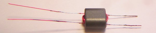
Install T1 with the longer leads toward R7 on the right.
INSTALL CAPACITORS:
DO NOT INSTALL CAPS C2,3,4,5. We will do this last.
Install the yellow cap (C7) first.
Install the 1000p polystyrene as shown in the below picture.
Install the electolytics last.
| C1 | 100n | blue | ________ |
| C2 | *6p8* | see text | ________ |
| C3 | 43p | NPO disc | ________ |
| C4 | 33p | NPO disc | ________ |
| C5 | 33p | NPO disc | ________ |
| C6 | 12p | NPO disc | ________ |
| C7 | 100n | yellow | ________ |
| C8 | 1200p | polystyrene | ________ |
| C9 | 100n | blue | ________ |
| C10 | 10u | electrolytic | ________ |
| C11 | 100n | blue | ________ |
| C12 | 220u | electrolytic | ________ |
| C13 | 100n | blue | ________ |
| C14 | 10u | electrolytic | ________ |
| C15 | 100n | blue | ________ |
| C16 | 100n | blue | ________ |
| C17 | 100n | blue | ________ |
| C18 | 100n | blue | ________ |
INSTALL SEMICONDUCTORS:
Make sure the outlines on the board match the parts.
| D1 | MV209 varactor diode | ________ |
| D2 | MV209 varactor diode | ________ |
| D3 | MPN3700 PIN diode (labeled D2 on top of the PCB) | ________ |
| D4 | MPN3700 PIN diode (labeled D3 on top of the PCB) | ________ |
| Q1 | J310 FET | ________ |
| Q2 | 2N3904 NPN transistor | ________ |
| Q3 | 2N3904 NPN transistor | ________ |
| U1 | 78L05 5V regulator | ________ |
| U2 | 78L10 10V regulator | ________ |
The "minor" tune toroid (L2) is a T37-2 with 35 turns of #28 wire.
Measure out exactly 18 inches or 46 cm from
the spool of 28 ga magnet wire.
Push half of the wire thru the toroid and start winding clockwise.
Toroid Winding Details Here
Make sure you have a tight wind on this toroid.
Do not cross/overlap the turns on the toroid.
Cut any excess lead length so that 1/2 inch remains.
Strip the insulation from the wire pigtails.
Use sandpaper as you do not want to nick the wire.
Install the toroid vertically per the picture below.
If you have headers available, install them now.
Adjust the 50K blue pot about half-way.
To measure an output from the VFO, we need to turn on one of the PIN diodes by placing +12V on either PIN-1 or PIN-3 of the J3 header.
Solder a small wire from one of the pins to +12V on the bottom of the PCB
Install a 43p and two (2) 33p caps at C3, C4 and C5 but do not solder.
Form the leads to these caps so they make contact on the PCB.
Connect a 10K pot (10-turn if available) to J1
The wiper of the pot must connect to the middle pin of J1
Connect 50 ohm load to the output and connect a scope to the load.
Slowly and carefully, apply 12V and ground to connector J2
observing current draw. Current should be about 39 milliamps.
If caps C3,4,and 5 are touching the circuits, you should see a waveform on your scope. The trick is to find the correct capacitor combination to give you your desired frequency coverage and it all depends on component tolerances and the way you wound L1 and L2.
Since I wanted to have coverage down to 7.000 KHz, my lowest VFO freq needs to be 1933 KHz since 1933 + 5067KHz(IF) = 7000 KHz
Find the correct cap combo and solder C2,3,4 and 5.
Included in the NPO capacitor inventory are 2-43p, 3-33p, 1-10p. 1-6p8, 1-3p
My VFO ended up with 1-43p, 2-33p and 1-6p8
Also included with this kit is 28 ga & 34 ga magnet wire.
Not included are the header pins and the tune pot.
Finally, adjust R5 for your output. 1.4V P-P = 7dBm