Available for 10, 12, 15, 17, 20, 30, 40, 80 and 160 meters.
When ordering, please specify the Band(s) you want in an EMAIL
or in the COMMENTS section of the PAYPAL order
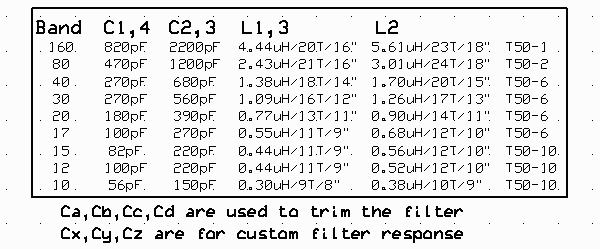
Specs: Values taken from Year 2000 ARRL Handbook, page 30.18
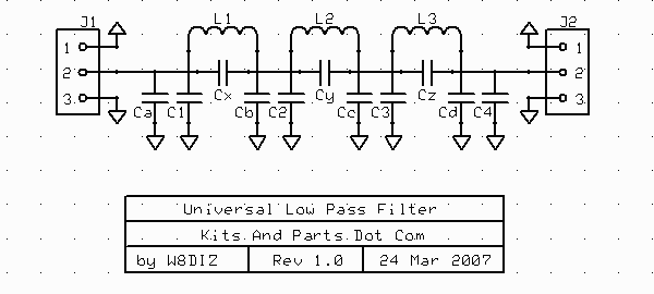
7 Element Chebyshev Low-Pass filter Designs for 50 ohm Impedance
Also reference this web-page by Revd. George Dobbs G3RJV for more information.
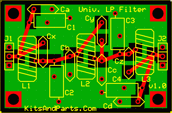
Capacitor hole locations Ca,Cb,Cc and Cd are available for fine tuning.
Capacitor hole locations Cx, Cy and Cz are available for custom filter designs.
Capacitors C1,C2,C3,C4 are included with the kit, as are L1,L2,L3 - FOR ONE BAND ONLY.


Instructions:
1. Install L1, L2 and L3.
a. Cut the spool of Copper Colored Magnet wire into 3 pieces per the above table.
b. Wind each toroid in a clockwise direction - Toroid Winding Details Here
c. Prepare the toroid wires for soldering - Magnet Wire Soldering Details Here
This magnet wire uses three layers of Epoxy insulation and is NOT heat stripable.
d. Install and solder the three toroid inductors. Note that L2 is in the middle.
2. Install C1, C2, C3 and C4.
a. Install capacitors into their correct places per the above table.
Polystyrene capacitors use the 0,45 inch hole spacing.
Disc capacitors use the 0,2 inch hole spacing.
Install into one ground hole only.
3. Connect the LPF via J1 and J2.