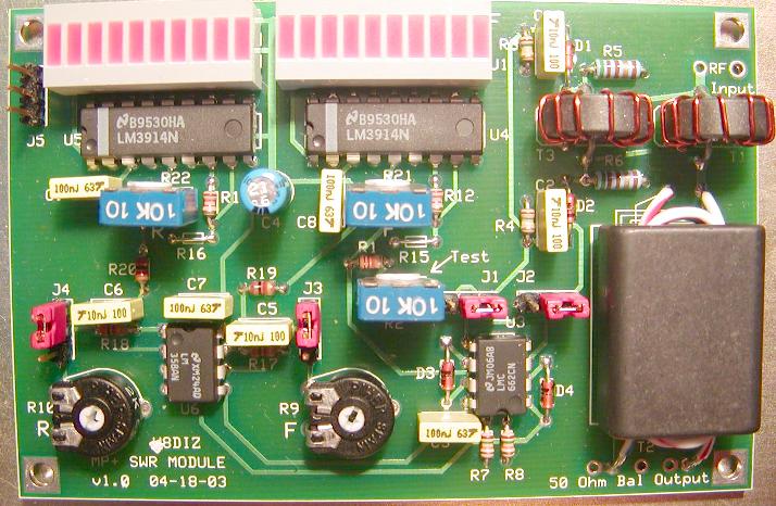
INSTRUCTIONS FOR BUILDING THE SWR-Kit, A component of the multiPIG+
updated 05/28/03 8:00 AM
The SWR kit includes the following:
1. XMTR PCB
2. Plastic bag with parts
3. wire
4. Schematic
We will build the SWR in this order:
0. Review instructions. Inspect PCB and parts.
1. Install resistors and Diodes
2. Install headers
3. Install ICs and displays
4. Install capacitors
5. Install all Pots.
6. Wind and install all toroids.
Ready...set...begin!
INVENTORY all the parts against the parts list.
 NOTE: R11 and R14 are not used.
R15 and R16 are wire shunts.
All resistors are 1/8W except R5 and R6
____ R12,R13 1k2 BROWN-RED-RED
____ R15,R16 ZERO Ohms (use cut resistor leads)
____ R5,R6 51 GREEN-BROWN-BLACK 1/4 Watt
_____R19,R20 1k BROWN-BLACK-RED
_____R17,R18 3k ORANGE-BLACK-RED
_____R7,R8 15k BROWN-GREEN-ORANGE
_____R1 22k RED-RED-ORANGE
_____R3,R4 150k BROWN-GREEN-YELLOW
Observe polarity when installing the diodes.
____ D1 1N5711 Diode
____ D2 1N5711 Diode
____ D3 1N5711 Diode
____ D4 1N5711 Diode
____ J1,J2,J3,J4,J5 3 pin headers
____ U6 LM358
____ U4,U5 LM3914
____ U1,U2 LEDx10
____ U3 LMC662
____ C1,C2,C5,C6 10n
____ C3 C7 C8 C9 100n
____ C4 22u
____ R2,R21,R22 10k pot
____ R9,R10 2k pot
____ T1 FT50-43 10 Turns (9" of #24)
____ T3 FT50-43 10 Turns (9" of #24)
NOTE: R11 and R14 are not used.
R15 and R16 are wire shunts.
All resistors are 1/8W except R5 and R6
____ R12,R13 1k2 BROWN-RED-RED
____ R15,R16 ZERO Ohms (use cut resistor leads)
____ R5,R6 51 GREEN-BROWN-BLACK 1/4 Watt
_____R19,R20 1k BROWN-BLACK-RED
_____R17,R18 3k ORANGE-BLACK-RED
_____R7,R8 15k BROWN-GREEN-ORANGE
_____R1 22k RED-RED-ORANGE
_____R3,R4 150k BROWN-GREEN-YELLOW
Observe polarity when installing the diodes.
____ D1 1N5711 Diode
____ D2 1N5711 Diode
____ D3 1N5711 Diode
____ D4 1N5711 Diode
____ J1,J2,J3,J4,J5 3 pin headers
____ U6 LM358
____ U4,U5 LM3914
____ U1,U2 LEDx10
____ U3 LMC662
____ C1,C2,C5,C6 10n
____ C3 C7 C8 C9 100n
____ C4 22u
____ R2,R21,R22 10k pot
____ R9,R10 2k pot
____ T1 FT50-43 10 Turns (9" of #24)
____ T3 FT50-43 10 Turns (9" of #24)
 Cut 2 pieces of 0.9 inch wire leads from 1/2W Resistor
Bend the wires into the chape of a "U" with the legs
0.2" and the bottom of the "U" at 0.3"
____ Install the "U" wires thru Toroids T1 and T3.
____ T2 BN-43-3312
2 Turns black wire primary
2 Turns black wire secondary
____ Place jumpers on pins 1 and 2 of J1 and J2
____ Place jumpers on pins 2 and 3 of J3 and J4
CALIBRATE THE SWR METER (pending)
CONNECT TO LPF
NEED HELP?
Email me ... w8diz at fpqrp.com
Cut 2 pieces of 0.9 inch wire leads from 1/2W Resistor
Bend the wires into the chape of a "U" with the legs
0.2" and the bottom of the "U" at 0.3"
____ Install the "U" wires thru Toroids T1 and T3.
____ T2 BN-43-3312
2 Turns black wire primary
2 Turns black wire secondary
____ Place jumpers on pins 1 and 2 of J1 and J2
____ Place jumpers on pins 2 and 3 of J3 and J4
CALIBRATE THE SWR METER (pending)
CONNECT TO LPF
NEED HELP?
Email me ... w8diz at fpqrp.com