Specs:
Greater than 20 dBm power gain from 2-30 MHz


Instructions:
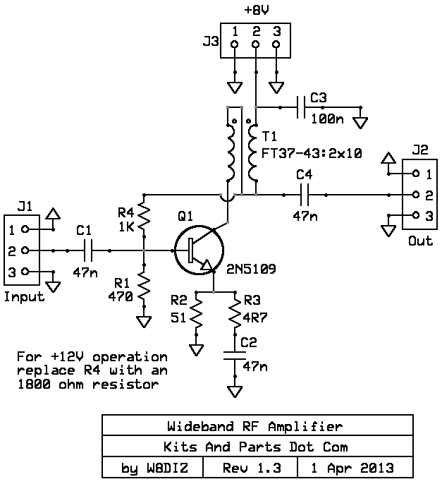
R4 is shown as 1K for 8 volt operation.
The kit uses a 2K for 12 volt operation.
1. Decide the output impedance of the RF Amp, 50 or 200 Ohms. Default is 50 ohms.
For 50 ohms, wind 10 turns bifilar using the included wire.
For 200 ohms, unwind the twisted pair magnet wire. Use one wire to make a 10 turn choke.
Prepare the toroid wires for soldering - Magnet Wire Soldering Details Here
This magnet wire uses multiple layers of insulation and is NOT heat stripable.
2. Install and solder T1.
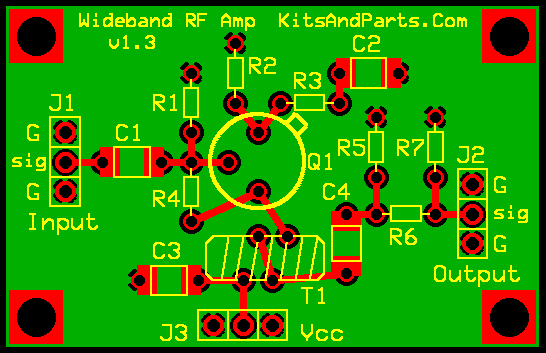
For 50 ohms, install per the PCB picture. Note the 2 different colors of the magnet wire.
One color wire should connect to J3/C3 and the other color connects to Q1
You should also have 2 different color wires connecting under the toroid via a PCB trace.
For 200 ohms, install the T1 between J3 at one end. The other end of T1
connects to Q1 and C4.
Then place a jumper wire from the lower left toroid hole to the upper left toroid hole.
This will connect Q1 and C4 to one leg of T1. The other leg of T1 connects to J3 and C3
4. Install Q1 to the PCB leaving about 1/16" (1 or 2 mm) space between the Q1 and the PCB
5. Install all remaining parts.
5. R5,6,7 are used to attenuate the rf output. Place a jumper wire across R6.
6. Connect the RF Amplifier via J1, J2 and J3.