INSTRUCTIONS FOR BUILDING THE RECEIVER, A component of the multiPIG+
updated 4/6/03 21:17 PM
The RCVR kit includes 6 plastic envelopes and a schematic.
1. RVCR PCB with 2 wires
2. 5 matched crystals and 4 matched varactor diodes
3. Headers, connectors and 6 black toroids and 2 red toroids
4. Resistors, capacitors and mixers.
We will build the RCVR in this order:
0. Review instructions. Inspect PCB and parts.
1. Wind all toroids (hardest part first)
2. Install SMT mixer parts
3. Install all resistors
4. Install all toroids
5. Install capacitors
6. Install the headers
7, Install all discrete components
8. Install the Crystals
9. Test voltage regulator
10. Interconnections to other MP+ components
11. Tune Up and calibration
Ready...set...begin!
INVENTORY all the parts against the parts list.
Be careful not to loose the 2 small short wires in the wire bag.
ERRORS Inspect the PCB. You will find two errors in the layout...
1. A cut in the trace on the back of the PCB behind L9 (lower middle)
We will add a jumper wire after all the other parts are installed.
2. A cut in the trace between R36 and C45 on top in lower left corner.
We will add capacitor C45 after all the other parts are installed.
MODS This modification was added to improve the PLL output waveform.
It your PCB does not have a TRACE CUT on the top of the board from
PIN 2 of J3 to the lower connection of L5, then do so now.
We will solder R21 across the CUT after all the other parts are installed.
WIND TOROIDS (note: there is no L1)
Seperate the 6 black toroids from the connector housing bag. There are three
FT37-43 and three FT37-61. The -61 are dull and gray while the -43 are shiny.
note: All toroids must be wound the same way or they will not fit into the PCB.
The correct winding direction should make the toroids look like this:
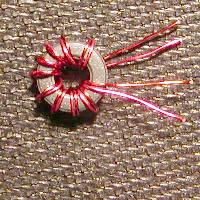
 ____L2 Wind 10 turns of the twisted pair wire onto an FT37-43 toroid evenly spaced.
Cut the 4 ends to about 1/2 inch from the body of the toroid. Note the two colors.
The toroid should look like this with the lead colors alternating.
____L2 Wind 10 turns of the twisted pair wire onto an FT37-43 toroid evenly spaced.
Cut the 4 ends to about 1/2 inch from the body of the toroid. Note the two colors.
The toroid should look like this with the lead colors alternating.
 ____L3 Wind 18 turns #27 brown wire on a FT37-61 toroid
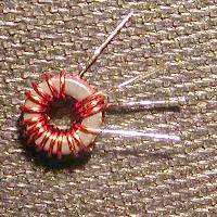
____L4 Wind 14 and 3 turns #24 brown wire on a red T37-2 toroid; see first picture above
____L5 and L8 Wind 10 turns #27 brown wire on a FT37-43 toroid
____L6 and L7 Wind 17 turns #27 brown wire on two FT37-61 toroids
(note: the wire for L9 is in the PCB bag)
____L9 binocular transformer (L9 instructions from Dennis - WB0WAO)
a. Take #32 wire (red) and insert from either side thru one hole...
b. Loop the wire and pass thru the other hole....
c. Wire will be in the shape of a "U" on its side - this is one turn...
d. Repeat this 5 more time to get 6 turns - both red wires will be sticking
out the same side...
e. Take #30 wire (green)and insert thru one of the holes on the OPPOSITE
side that you started the red wire..
f. Loop the wire and pass thru the other hole....
g. Wire will be in the shape of a "U" on its side - this is one turn...
h. Do this once more to get 2 turns - both green wires will be sticking out
the same side...
i. Install with the end with the red wires coming out towards U4 and the
green wires should be towards X6
____L10 wind 31 turns #28 ga red wire on a red T37-2 toroid
____L3 Wind 18 turns #27 brown wire on a FT37-61 toroid
____L4 Wind 14 and 3 turns #24 brown wire on a red T37-2 toroid; see first picture above
____L5 and L8 Wind 10 turns #27 brown wire on a FT37-43 toroid
____L6 and L7 Wind 17 turns #27 brown wire on two FT37-61 toroids
(note: the wire for L9 is in the PCB bag)
____L9 binocular transformer (L9 instructions from Dennis - WB0WAO)
a. Take #32 wire (red) and insert from either side thru one hole...
b. Loop the wire and pass thru the other hole....
c. Wire will be in the shape of a "U" on its side - this is one turn...
d. Repeat this 5 more time to get 6 turns - both red wires will be sticking
out the same side...
e. Take #30 wire (green)and insert thru one of the holes on the OPPOSITE
side that you started the red wire..
f. Loop the wire and pass thru the other hole....
g. Wire will be in the shape of a "U" on its side - this is one turn...
h. Do this once more to get 2 turns - both green wires will be sticking out
the same side...
i. Install with the end with the red wires coming out towards U4 and the
green wires should be towards X6
____L10 wind 31 turns #28 ga red wire on a red T37-2 toroid
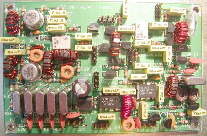 This picture does not show the 3 headers for the PreAmp
It is hard wired to always have the preamp ON.
Also, this version of the RCVR PCB does not use varaactors.
I wanted to test using 330pF fixed caps for the IF XTAL filter.
SMT MIXERS These are the only two surface mount parts.
Remove the mixers from the resistor bag. Carefully scrape the white paint off of the pads
for U1 and U2 on the top of the PCB. Use a small blade screwdriver. You will need fine tip
solder pencil for the SMT mixers. Also, you can position the mixers either way on the PCB.
They are symetrical in pin layout so there is no way to mount them wrong (except for Phil)
____Position U2 on the PCB and align the 6 contacts with the 6 pads. Tack one lead to the
PCB. Solder the other pads to the PCB, then solder the first pad to the PCB.
____Do the same for U1.
Install and solder ALL the resistors.
If you are visually challanged like me, use a magnifying glass to identify the resistors.
Clip the leads close to the board after soldering.
Suggest you install the resistors in this order:
push all resistors flush against the PCB.
NOTE: Save 6 clipped resistor leads for the XTALs.
These will be used to ground the XTAL cans.
____R7 4R7 YELLOW-PURPLE-GOLD top left edge of PCB
____R33 4R7 YELLOW-PURPLE-GOLD to the right of Q6 left center
____R11 27 RED-VIOLET-BLACK between Q2 and Q3 right center
____R22 27 RED-VIOLET-BLACK right center of PCB
____R23 27 RED-VIOLET-BLACK right center below R22
____R9 51 GREEN-BROWN-BLACK top left edge of PCB
____R20 51 GREEN-BROWN-BLACK slightly left of center of PCB
____R38 51 GREEN-BROWN-BLACK just above the Xtal Filter
____R32 75 VIOLET-GREEN-BLACK just left of Xtal Filter
____R19 220 RED-RED-BROWN center of PCB
____R26 120 BROWN-RED-BROWN between U3 and U5 near center
CAUTION: DO NOT MIX UP R10, A 300 ohm WITH A 10K RESISTOR
____R10 300 ORANGE-BLACK-BROWN right center of PCB
____R2 470 YELLOW-VIOLET-BROWN upper left corner
____R24 470 YELLOW-VIOLET-BROWN left above Q6
____R35 750 VIOLET-GREEN-BROWN left of Xtal Filter
____R36 750 VIOLET-GREEN-BROWN left of Xtal Filter
____R1 1K BROWN-BLACK-RED upper left corner
____R3 1K BROWN-BLACK-RED right edge center
____R4 1K BROWN-BLACK-RED above U2 mixer
____R5 1K BROWN-BLACK-RED upper center edge
____R12 1K BROWN-BLACK-RED right of U2 near center
____R13 1K BROWN-BLACK-RED below U1 center
____R14 1K BROWN-BLACK-RED upper right corner
____R17 1K BROWN-BLACK-RED right of U1
____R25 1K BROWN-BLACK-RED left of Q6
____R18 1K2 BROWN-RED-RED right of U3 near center of PCB
____R6 5K6 GREEN=BLUE-RED center right edge of PCB
____R8 10K BROWN-BLACK-ORANGE above X1 right edge
____R15 10K BROWN-BLACK-ORANGE lower right corner
____R16 10K BROWN-BLACK-ORANGE lower right corner
____R31 10K BROWN-BLACK-ORANGE right, bottom edge corner
____R34 10K BROWN-BLACK-ORANGE right, bottom edge corner
____R27 100K BROWN-BLACK-YELLOW below Xtal Filter
____R28 100K BROWN-BLACK-YELLOW below Xtal Filter
____R29 100K BROWN-BLACK-YELLOW below Xtal Filter
____R30 100K BROWN-BLACK-YELLOW below Xtal Filter
____R37 1M BROWN-BLACK-GREEN between U5 and bottom right corner
INSTALL TOROIDS
____L2 Install L2. The outer windings should be different color wire
as should be the inner wires. Upper left corner.
____L3 lower right
____L4 Upper right. The 14 turn winding wires must be soldered in the upper
and lower holes. The middle (inline) holes are for the 3 turn winding.
NOTE: There is an extra hole in the PCB on the trace that connects D6 and L4
This can be used to measure the BFO frequency and to align the XTAL filter
and the XMIT offset. More to follow when we align the RCVR
____L5 Center of board
____L6 Left Center
____L7 Left Center
____L8 Far Left
____L9 Red wires toward U4, the MC1350
____L10 just to the right of U4
INSTALL CAPACITORS
____C21 43pf near Q6
____C44 43pf near Q6
____C14 [Brown or Yellow] 50pF Var Flat edge toward XTAL X1
____C15 [Brown or Yellow] 50pF Var Flat edge toward XTAL X1
____C20 [Orange] 80pF Var Flat edge toward left edge of PCB near Q6
____C24 [Orange] 80pF Var Flat edge toward left edge of PCB near Q6
____C42 [Orange] 80pF Var Flat edge toward L10 bottom edge
____C38 130pF below U5
____C4 220pF above X1
____C43 220pF below U5
____C1 330pF above X1 right edge
____C25 1000pF above U5
____C11 1500pF upper right corner
____C33 47n (22n in schematic) below X1 bottom edge
note:C13 is a bit tight but will fit OK
____C2 10n right of Q1 on top edge
____C5 10n below C2 right of Q1
____C6 10n left of U1 mixer
____C7 10n above C2 right of Q1
____C9 10n right of U1 mixer
____C12 10n upper left center of PCB
____C13 10n upper right center of PCB
____C16 10n below C12 [* SEE SPECIAL NOTE IN HEADER INSTALLATIONS]
____C17 10n below C13
____C19 10n lower right corner
____C23 10n middle right center
____C39 10n right of U5
____C41 10n below U5 bottom edge
The following caps are the Yellow Box shapes
____C3 100n radial near upper edge center of PCB
____C10 100n radial left edge below L2
____C18 100n radial top right corner
____C22 100n radial lower right of U1
____C27 100n radial middle left edge
____C30 100n radial above U4 near center of PCB
____C31 100n radial above U5
____C32 100n radial near Pin 8 of U5
____C34 100n radial above pin 8 of U5
____C40 100n radial below U5 near bottom edge
____C8 100n axial just below Q1
____C28 100n axial below X2 bottom edge
____C29 100n axial below X6 bottom edge
____C35 100n axial left of Q6 near left edge
____C37 100n axial above X6
____C26 220uF above and right of X6 near center of PCB
The next 2 caps can be modified. The are part of the IF BandPass Filter.
____C36 220pF beolow X6
____C45 220pF this cap will be soldered on the bottom of the PCB (later)
INSTALL HEADERS
____J1 3PIN center near top edge
____J2 3PIN right of Q1
____J3 3PIN center of PCB
____J4 3PIN below Q1
____J5 3PIN below Q1 on left edge
____J6 3PIN center of PCB
____J7 3PIN above J6
*NOTE: The right side of C16 should be grounded. PLACE A SOLDER BRIDGE
between the right side of C16 and the top pin of J7 on the bottom of
the RCVR PCB. This will ground the right pin of C16.
These two points are next to each other on the bottom of the PCB.
____J8 3PIN right top edge
____J9 3PIN bottom edge below U5
____J10 3PIN bottom edge center
____J11 3PIN below X6 bottom edge
____J12 3PIN near center below U1
INSTALL DISCRETE COMPONENTS
____D7 1N4148 near lower right corner
Install the PIN diodes about 1/16 inch above the PCB
____D1 D2 MPN3700 upper center of PCB
____D3 D4 MPN3700 below D1 and D2
____D5 D6 MPN3700 near upper right corner
Install the next parts about 3/16 inch above the PCB
____Q2 2N3904 near right edge center
____Q4 2N3904 near right edge lower corner
____Q5 2N3904 bottom edge near right corner
____Q3 2N3906 near right edge center
____Q7 J310 (J201 in schematic) left of Q5 near bottom edge right
____U3 LM317L center of PCB
Install the 2N5109s and/or MRF517 about 1/16 inch above the PCB
____Q1 MRF517 or 2N5109 upper left corner
____Q6 MRF517 or 2N5109 middle left edge
____U4 MC1350 middle near lower edge
*** CAUTION ***
YOU MUST BREAK OFF PINS 5 and 7 on the SA602AM
____U5 SA602AN middle of lower right quadrant
INSTALL CRYSTALS
When soldering the XTALs, tilt the XTALs 10 or 15 degrees
This will keep the metal can from shorting out any traces
below the XTALs.
____X1 4.9152 BFO Xtal right edge middle
____X2 X3 X4 X5 X6 4.9152 Xtal Filter
The next two steps will connect the metal XTAL cans to ground
solder a wire from the hole to the right of X1 to the side of X1
____X1
solder a wire from the holes above the XTALS to the side of XTALs
____X2 X3 X4 X5 X6
Install the VARACTOR diodes about 1/16 inch above the PCB
____D8 D9 D10 D11 MVAM109 lower left corner on bottom edge
This picture does not show the 3 headers for the PreAmp
It is hard wired to always have the preamp ON.
Also, this version of the RCVR PCB does not use varaactors.
I wanted to test using 330pF fixed caps for the IF XTAL filter.
SMT MIXERS These are the only two surface mount parts.
Remove the mixers from the resistor bag. Carefully scrape the white paint off of the pads
for U1 and U2 on the top of the PCB. Use a small blade screwdriver. You will need fine tip
solder pencil for the SMT mixers. Also, you can position the mixers either way on the PCB.
They are symetrical in pin layout so there is no way to mount them wrong (except for Phil)
____Position U2 on the PCB and align the 6 contacts with the 6 pads. Tack one lead to the
PCB. Solder the other pads to the PCB, then solder the first pad to the PCB.
____Do the same for U1.
Install and solder ALL the resistors.
If you are visually challanged like me, use a magnifying glass to identify the resistors.
Clip the leads close to the board after soldering.
Suggest you install the resistors in this order:
push all resistors flush against the PCB.
NOTE: Save 6 clipped resistor leads for the XTALs.
These will be used to ground the XTAL cans.
____R7 4R7 YELLOW-PURPLE-GOLD top left edge of PCB
____R33 4R7 YELLOW-PURPLE-GOLD to the right of Q6 left center
____R11 27 RED-VIOLET-BLACK between Q2 and Q3 right center
____R22 27 RED-VIOLET-BLACK right center of PCB
____R23 27 RED-VIOLET-BLACK right center below R22
____R9 51 GREEN-BROWN-BLACK top left edge of PCB
____R20 51 GREEN-BROWN-BLACK slightly left of center of PCB
____R38 51 GREEN-BROWN-BLACK just above the Xtal Filter
____R32 75 VIOLET-GREEN-BLACK just left of Xtal Filter
____R19 220 RED-RED-BROWN center of PCB
____R26 120 BROWN-RED-BROWN between U3 and U5 near center
CAUTION: DO NOT MIX UP R10, A 300 ohm WITH A 10K RESISTOR
____R10 300 ORANGE-BLACK-BROWN right center of PCB
____R2 470 YELLOW-VIOLET-BROWN upper left corner
____R24 470 YELLOW-VIOLET-BROWN left above Q6
____R35 750 VIOLET-GREEN-BROWN left of Xtal Filter
____R36 750 VIOLET-GREEN-BROWN left of Xtal Filter
____R1 1K BROWN-BLACK-RED upper left corner
____R3 1K BROWN-BLACK-RED right edge center
____R4 1K BROWN-BLACK-RED above U2 mixer
____R5 1K BROWN-BLACK-RED upper center edge
____R12 1K BROWN-BLACK-RED right of U2 near center
____R13 1K BROWN-BLACK-RED below U1 center
____R14 1K BROWN-BLACK-RED upper right corner
____R17 1K BROWN-BLACK-RED right of U1
____R25 1K BROWN-BLACK-RED left of Q6
____R18 1K2 BROWN-RED-RED right of U3 near center of PCB
____R6 5K6 GREEN=BLUE-RED center right edge of PCB
____R8 10K BROWN-BLACK-ORANGE above X1 right edge
____R15 10K BROWN-BLACK-ORANGE lower right corner
____R16 10K BROWN-BLACK-ORANGE lower right corner
____R31 10K BROWN-BLACK-ORANGE right, bottom edge corner
____R34 10K BROWN-BLACK-ORANGE right, bottom edge corner
____R27 100K BROWN-BLACK-YELLOW below Xtal Filter
____R28 100K BROWN-BLACK-YELLOW below Xtal Filter
____R29 100K BROWN-BLACK-YELLOW below Xtal Filter
____R30 100K BROWN-BLACK-YELLOW below Xtal Filter
____R37 1M BROWN-BLACK-GREEN between U5 and bottom right corner
INSTALL TOROIDS
____L2 Install L2. The outer windings should be different color wire
as should be the inner wires. Upper left corner.
____L3 lower right
____L4 Upper right. The 14 turn winding wires must be soldered in the upper
and lower holes. The middle (inline) holes are for the 3 turn winding.
NOTE: There is an extra hole in the PCB on the trace that connects D6 and L4
This can be used to measure the BFO frequency and to align the XTAL filter
and the XMIT offset. More to follow when we align the RCVR
____L5 Center of board
____L6 Left Center
____L7 Left Center
____L8 Far Left
____L9 Red wires toward U4, the MC1350
____L10 just to the right of U4
INSTALL CAPACITORS
____C21 43pf near Q6
____C44 43pf near Q6
____C14 [Brown or Yellow] 50pF Var Flat edge toward XTAL X1
____C15 [Brown or Yellow] 50pF Var Flat edge toward XTAL X1
____C20 [Orange] 80pF Var Flat edge toward left edge of PCB near Q6
____C24 [Orange] 80pF Var Flat edge toward left edge of PCB near Q6
____C42 [Orange] 80pF Var Flat edge toward L10 bottom edge
____C38 130pF below U5
____C4 220pF above X1
____C43 220pF below U5
____C1 330pF above X1 right edge
____C25 1000pF above U5
____C11 1500pF upper right corner
____C33 47n (22n in schematic) below X1 bottom edge
note:C13 is a bit tight but will fit OK
____C2 10n right of Q1 on top edge
____C5 10n below C2 right of Q1
____C6 10n left of U1 mixer
____C7 10n above C2 right of Q1
____C9 10n right of U1 mixer
____C12 10n upper left center of PCB
____C13 10n upper right center of PCB
____C16 10n below C12 [* SEE SPECIAL NOTE IN HEADER INSTALLATIONS]
____C17 10n below C13
____C19 10n lower right corner
____C23 10n middle right center
____C39 10n right of U5
____C41 10n below U5 bottom edge
The following caps are the Yellow Box shapes
____C3 100n radial near upper edge center of PCB
____C10 100n radial left edge below L2
____C18 100n radial top right corner
____C22 100n radial lower right of U1
____C27 100n radial middle left edge
____C30 100n radial above U4 near center of PCB
____C31 100n radial above U5
____C32 100n radial near Pin 8 of U5
____C34 100n radial above pin 8 of U5
____C40 100n radial below U5 near bottom edge
____C8 100n axial just below Q1
____C28 100n axial below X2 bottom edge
____C29 100n axial below X6 bottom edge
____C35 100n axial left of Q6 near left edge
____C37 100n axial above X6
____C26 220uF above and right of X6 near center of PCB
The next 2 caps can be modified. The are part of the IF BandPass Filter.
____C36 220pF beolow X6
____C45 220pF this cap will be soldered on the bottom of the PCB (later)
INSTALL HEADERS
____J1 3PIN center near top edge
____J2 3PIN right of Q1
____J3 3PIN center of PCB
____J4 3PIN below Q1
____J5 3PIN below Q1 on left edge
____J6 3PIN center of PCB
____J7 3PIN above J6
*NOTE: The right side of C16 should be grounded. PLACE A SOLDER BRIDGE
between the right side of C16 and the top pin of J7 on the bottom of
the RCVR PCB. This will ground the right pin of C16.
These two points are next to each other on the bottom of the PCB.
____J8 3PIN right top edge
____J9 3PIN bottom edge below U5
____J10 3PIN bottom edge center
____J11 3PIN below X6 bottom edge
____J12 3PIN near center below U1
INSTALL DISCRETE COMPONENTS
____D7 1N4148 near lower right corner
Install the PIN diodes about 1/16 inch above the PCB
____D1 D2 MPN3700 upper center of PCB
____D3 D4 MPN3700 below D1 and D2
____D5 D6 MPN3700 near upper right corner
Install the next parts about 3/16 inch above the PCB
____Q2 2N3904 near right edge center
____Q4 2N3904 near right edge lower corner
____Q5 2N3904 bottom edge near right corner
____Q3 2N3906 near right edge center
____Q7 J310 (J201 in schematic) left of Q5 near bottom edge right
____U3 LM317L center of PCB
Install the 2N5109s and/or MRF517 about 1/16 inch above the PCB
____Q1 MRF517 or 2N5109 upper left corner
____Q6 MRF517 or 2N5109 middle left edge
____U4 MC1350 middle near lower edge
*** CAUTION ***
YOU MUST BREAK OFF PINS 5 and 7 on the SA602AM
____U5 SA602AN middle of lower right quadrant
INSTALL CRYSTALS
When soldering the XTALs, tilt the XTALs 10 or 15 degrees
This will keep the metal can from shorting out any traces
below the XTALs.
____X1 4.9152 BFO Xtal right edge middle
____X2 X3 X4 X5 X6 4.9152 Xtal Filter
The next two steps will connect the metal XTAL cans to ground
solder a wire from the hole to the right of X1 to the side of X1
____X1
solder a wire from the holes above the XTALS to the side of XTALs
____X2 X3 X4 X5 X6
Install the VARACTOR diodes about 1/16 inch above the PCB
____D8 D9 D10 D11 MVAM109 lower left corner on bottom edge
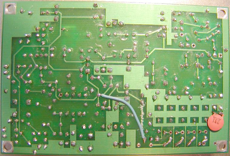 Note the 330pF cap on the bottom of the PCB.
This value should be 220pF (C45) that comes with the kit.
____Install C45 220pF disk cap on the bottom of the PCB per picture
Do not install in the holes marked C45
____Jumper - On the bottom of the PCB, connect a small 1.25 inch
insulated wire from the right pin of J11 (between the pins of C29)
to the left side of C32. This is the point on the bottom of the
PCB that has FOUR circuit paths interconnect.
____R21 51 GREEN-BROWN-BLACK install on the bottom of the RCVR PCB
between Pin 2 of J3 and the junction of PIN diodes D3 and D4.
Note the cut trace on the top of the PCB as a reference.
____Replace 10.24 MHz xtal on the PLL PCB with the included 12.096 MHz.
TEST VOLTAGE REGULATOR LM317L
____Apply 12 volts to the center pin of J6 in the center of the PCB
Measure 8 volts on PIN 1, the lower pin of J12
INTERCONNECT THE RCVR PCB TO OTHER MP+ PCBs
____This requires that ALL PCBs are completed except the XMTR PCB
This step will be detailed in a forthcoming document
TUNE UP, ALIGNMENT AND CALIBRATION
BFO alignment instructions for the RCVR using a Scope.
MP+ Freq Counter (does not need to be calibrated)
1. Solder a 5" insulated wire to the test point on the
top side of the RCVR board. The test point is the vacant
hole between D5 and D6.
2. Connect all wires between the RCVR and the FCC.
3. Run the 5" wire through the center of L6 and connect the
free end to the Freq Counter.
4. Disable the Freq Counter Offset jumper J51
5. Connect the Oscilloscope to PIN 8 of U4 on the RCVR board.
6. Power up the RCVR/FCC
7. Set to Varactor voltage (J11 center pin) to 1.00 Volts.
8. Place the MP+ into XMIT mode; place jumper on J2 on the FCC
9. Adjust C14 AND C15 for a MAXIMUM PEAK signal. This should
be near 4,913,700 Hz. This is the XMIT BFO freq.
At this point, you need to decide on your favorite audio CW note.
Most CW operators like to listen to 600 to 700 Hz signals.
Calculate the RCVE BFO freq by adding your desired audio freq
to the XMTR BFO freq. In this example, my favorite audio freq
is near 700 Hz so the calculated RCVR BFO freq = 4,914,400
10. Place the MP+ into RCVE mode; remove J2 jumper
11. Adjust C14 on the RCVR to 4,914,400 or YOUR freq.
12. Place the MP+ into XMIT mode; replace J2 jumper
13. Adjust C15 on the RCVR to 4,913,700 or YOUR freq.
14. Repeat steps 10 thru 13 until there is no more
interaction between C14 and C15 adjustments.
BFO alignment instructions for the RCVR without using a Scope.
MP+ Freq Counter (does not need to be calibrated)
The BPF must be aligned before calibrating the BFO.
1. Interconnect all six MP+ PC boards along
with all controls and the speaker.
2. Connect the Freq Counter to the test point in the vacant
hole between D5 and D6. If you have not soldered a small
wire to the test point, do so now; about 1/2" will do.
3. Disable the Freq Counter Offset jumper J51
4. Connect an antenna to the BPF on the 40 meter port
Enable the RCVR PreAmp with jumpers J2, J4 and J5.
5. Power up the MP+
6. Set the PLL to 7040 on 40 meters
7. Set to Varactor voltage (J11 center pin) to 1.00 Volts.
8. Also adjust C14, C15, C20, C24 and C42 for maximum speaker noise.
9. Listen to a signal source from the antenna; either a CW QSO or
a locally generated signal. Tune across the signal and lock it
to a comfortable audio peak frequency near 700 Hz.
You will have to adjust C14 and C15 again to accomplish this.
Make sure that when you tune across the CW note that the signal
drops out of the Xtal Filter bandpass at high audio freqs and
also that the signal is NOT audible on the other sideband.
When you find a good adjustment for C14 and C15, check the
Freq Counter. It should read near 4,914,400 Hz +/- 100 Hz
This is the RCVE BFO freq.
Calculate the XMIT BFO freq by subtracting your desired audio freq
to the RCVR BFO freq. In this example, my favorite audio freq
is near 700 Hz so the calculated XMTR BFO freq = 4,913,700
10. Place the MP+ into XMIT mode; place jumper on J2
11. Adjust C15 on the RCVR to 4,913,700 or YOUR freq.
12. Place the MP+ into RCVE mode; remove J2 jumper
13. Adjust C14 on the RCVR to 4,914,400 or YOUR freq.
14. Repeat steps 10 thru 13 until there is no more
interaction between C14 and C15 adjustments.
NEED HELP?
Email me ... w8diz at fpqrp.com
Note the 330pF cap on the bottom of the PCB.
This value should be 220pF (C45) that comes with the kit.
____Install C45 220pF disk cap on the bottom of the PCB per picture
Do not install in the holes marked C45
____Jumper - On the bottom of the PCB, connect a small 1.25 inch
insulated wire from the right pin of J11 (between the pins of C29)
to the left side of C32. This is the point on the bottom of the
PCB that has FOUR circuit paths interconnect.
____R21 51 GREEN-BROWN-BLACK install on the bottom of the RCVR PCB
between Pin 2 of J3 and the junction of PIN diodes D3 and D4.
Note the cut trace on the top of the PCB as a reference.
____Replace 10.24 MHz xtal on the PLL PCB with the included 12.096 MHz.
TEST VOLTAGE REGULATOR LM317L
____Apply 12 volts to the center pin of J6 in the center of the PCB
Measure 8 volts on PIN 1, the lower pin of J12
INTERCONNECT THE RCVR PCB TO OTHER MP+ PCBs
____This requires that ALL PCBs are completed except the XMTR PCB
This step will be detailed in a forthcoming document
TUNE UP, ALIGNMENT AND CALIBRATION
BFO alignment instructions for the RCVR using a Scope.
MP+ Freq Counter (does not need to be calibrated)
1. Solder a 5" insulated wire to the test point on the
top side of the RCVR board. The test point is the vacant
hole between D5 and D6.
2. Connect all wires between the RCVR and the FCC.
3. Run the 5" wire through the center of L6 and connect the
free end to the Freq Counter.
4. Disable the Freq Counter Offset jumper J51
5. Connect the Oscilloscope to PIN 8 of U4 on the RCVR board.
6. Power up the RCVR/FCC
7. Set to Varactor voltage (J11 center pin) to 1.00 Volts.
8. Place the MP+ into XMIT mode; place jumper on J2 on the FCC
9. Adjust C14 AND C15 for a MAXIMUM PEAK signal. This should
be near 4,913,700 Hz. This is the XMIT BFO freq.
At this point, you need to decide on your favorite audio CW note.
Most CW operators like to listen to 600 to 700 Hz signals.
Calculate the RCVE BFO freq by adding your desired audio freq
to the XMTR BFO freq. In this example, my favorite audio freq
is near 700 Hz so the calculated RCVR BFO freq = 4,914,400
10. Place the MP+ into RCVE mode; remove J2 jumper
11. Adjust C14 on the RCVR to 4,914,400 or YOUR freq.
12. Place the MP+ into XMIT mode; replace J2 jumper
13. Adjust C15 on the RCVR to 4,913,700 or YOUR freq.
14. Repeat steps 10 thru 13 until there is no more
interaction between C14 and C15 adjustments.
BFO alignment instructions for the RCVR without using a Scope.
MP+ Freq Counter (does not need to be calibrated)
The BPF must be aligned before calibrating the BFO.
1. Interconnect all six MP+ PC boards along
with all controls and the speaker.
2. Connect the Freq Counter to the test point in the vacant
hole between D5 and D6. If you have not soldered a small
wire to the test point, do so now; about 1/2" will do.
3. Disable the Freq Counter Offset jumper J51
4. Connect an antenna to the BPF on the 40 meter port
Enable the RCVR PreAmp with jumpers J2, J4 and J5.
5. Power up the MP+
6. Set the PLL to 7040 on 40 meters
7. Set to Varactor voltage (J11 center pin) to 1.00 Volts.
8. Also adjust C14, C15, C20, C24 and C42 for maximum speaker noise.
9. Listen to a signal source from the antenna; either a CW QSO or
a locally generated signal. Tune across the signal and lock it
to a comfortable audio peak frequency near 700 Hz.
You will have to adjust C14 and C15 again to accomplish this.
Make sure that when you tune across the CW note that the signal
drops out of the Xtal Filter bandpass at high audio freqs and
also that the signal is NOT audible on the other sideband.
When you find a good adjustment for C14 and C15, check the
Freq Counter. It should read near 4,914,400 Hz +/- 100 Hz
This is the RCVE BFO freq.
Calculate the XMIT BFO freq by subtracting your desired audio freq
to the RCVR BFO freq. In this example, my favorite audio freq
is near 700 Hz so the calculated XMTR BFO freq = 4,913,700
10. Place the MP+ into XMIT mode; place jumper on J2
11. Adjust C15 on the RCVR to 4,913,700 or YOUR freq.
12. Place the MP+ into RCVE mode; remove J2 jumper
13. Adjust C14 on the RCVR to 4,914,400 or YOUR freq.
14. Repeat steps 10 thru 13 until there is no more
interaction between C14 and C15 adjustments.
NEED HELP?
Email me ... w8diz at fpqrp.com