The FPqrp Club miniPIG-10
MiniPIG-10 Builders and Owners
Specifications - 13 Dec 1999
| Designed for home & Field use |
RIT +/- 2KHz |
1000 mW nominal adjustable power output |
| 8 Vdc thru 15 Vdc voltage capable |
very low noise RF preamp |
Main freq control from VXO Osc |
| ASAP - as small as possible |
VXO Osc 19.991-20.001 MHz |
|
| High performance QRP |
4 pole xtal filter 8,063.5 KHz |
Very small antenna tuner (option) |
| Crystal control from 28.055 thru 28.065 MHz |
AGC - YES |
Single LED swr/pwr indicator (option) |
| Single conversion |
Fixed BFO @ 8,064 KHz |
Balanced or single ended output (option) |
| Diode ring rcve mixer |
Single stage audio filter/amp |
RF volts (option) |
| |
|
Analog Meter (option) |
miniPIG-10 Schematics & Parts List
Rev 0.4
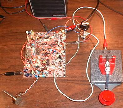
Pictures of ProtoType #1
Final Amp |

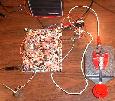
SWR indicator |
Xmtr prototype |

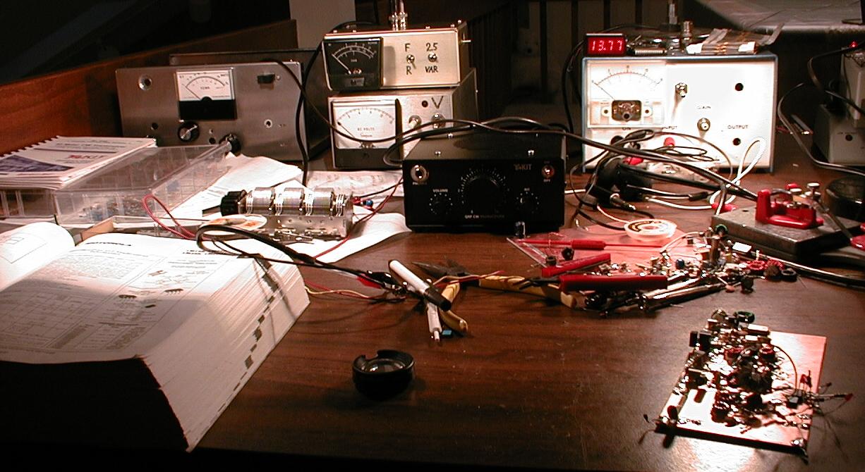
The work bench |
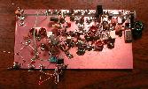
ProtoType #2
| This thing got half built and then trashed! |
Pictures of ProtoType #3 (MP#1 - 1st official miniPIG)
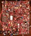
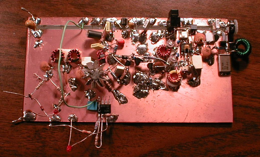
Here is the PCB for proto #3 |
Had 1st qso with this board on 5th Dec, 1999
Dave, FY/DJ0PJ, Kourou, French Guiana.
He gave me a 569! |
miniPIG-10 Design Notes
2000-MAY-02
miniPIG #5 is on the air. Ed Kessler, AA3SJ works W3TS. (not quite DX)
2000-MAR-26
Shipped miniPIG #3 to NA6E. Had HISTORIC miniPIG#2 to miniPIG#3 qso between
Mary NA6E and Diz WB8QYY.
2000-MAR-08
Build miniPIG #3. Works just like the first two unit.
2000-FEB-14
Started the miniPIG email reflector.
www.egroups.com/group/minipig - (no longer active)
1999-DEC-13
Schematic of the miniPIG-10 is now available as a GIF file.
Build miniPIG #2. Works just like the first unit. Added optional AGC and
optional RF voltmeter. Made a few contacts to confirm everything is OK. :-)
1999-DEC-07
After making 6 or 7 contacts with the miniPIG-10 prototype it's time for the schematics.
All are on line here now. Next step is to build a copy of the prototype.
1999-DEC-05
Built final prototype all day Saturday thru Sunday noon! Put the miniPIG-10 prototype on power and
called CQ. WOW!!! FY/DJ0PJ Dave in Kourou, French Guiana !!! Sent a 559; first received 439;
Then he changed it to 569. He was running 5 watt also into a dipole.
1999-NOV-30
I measured 130 pieces of 8.064 IF Xtals last night. I'm sorting these for the bandpass filters and BFO.
I expect to get a yield of 25 xtal kits. The new xmit mixer circuit uses a SBL-1 high level mixer.
Filtered output is large signal AND LOW Z for more stable circuit at 28 MHz.
Built a manual sweep generator for testing the IF bandpass filters
Currently, the freq mixing scheme is as follows:
Rcve BFO is at 8,064; Xmit is 8,063.5 or 500 Hz lower;
IF bandpass center freq is approx 8,063.5 ; VXO is about 20,002 KHz to 19,991 Khz or
RIT is connected to VXO; about 2 KHz range, depending on band section
miniPIG-10 overall tune range is from about 28,055 to 28,066
1999-NOV-13
Still working on proto #2. Started on proto #3 using new construction; Glue copper foil on bottom of
tenth inch hole plexiglass perf board. Insert parts into holes and remove copper. Pictures coming.
1999-NOV-07
Built the receiver section. This receiver is HOT! I'll spend the rest of the week cleaning it up.
Also working on tuneup and alignment procedures. I may build a couple of test jigs for this projects.
I used four (4) crystals for the bandpass filter in the IF strip. !st mixer is SBL-1 diode ring.
BFO mixer/detector is NE602. If amp is MC1350. I may change the IF amp; it's a bit noisy.
1999-NOV-02
Completed the redesign of the transmitter driver and output section. Seems very stable.
About half watt output at 12 vdc. Driver and xmit mixer are switched ON when keying.
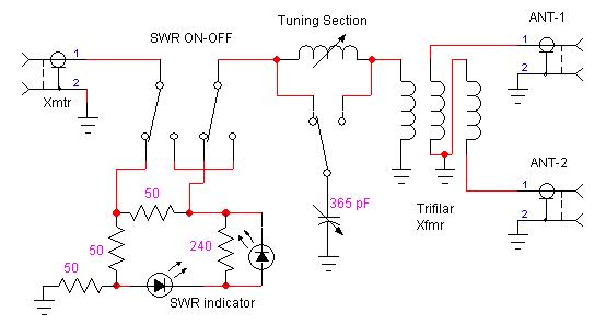
I'll wire in SWR led indicator and L network for swr tuning next.
1999-NOV-01
Finished buffer amp and adjustable power output circuit. Very stable (so far)
Doing the driver and final amp now.
1999-OCT-31
Gettin back on the project. Too much time spent on FPqrp web stuff and QSO's & contests.
Am building another transmitter with a different version of buffer amplifier. Power output will
be fully adjustable from 0 to max.
1999-SEP-09
Back for more fun & games. Designed the SWR meter / Antenna tuner. Works great. See schematic.
Also removed the swr switch from the PA and made it a seperate item.
1999-AUG-30
The miniPIG-10 design is on hold until after my vacation. The transmitter section
is basically finished. Final design on xmtr will be the QSK circuit.
1999-AUG-24
Posted the miniPIG-10 PA schematic.
1999-AUG-23
Took the day off from design to work on my 40 meter vertical phased array!
1999-AUG-22
What a day! Decided to rip off the driver circuit design from my Tentec 1340 QRP rig. Seems to work ok,
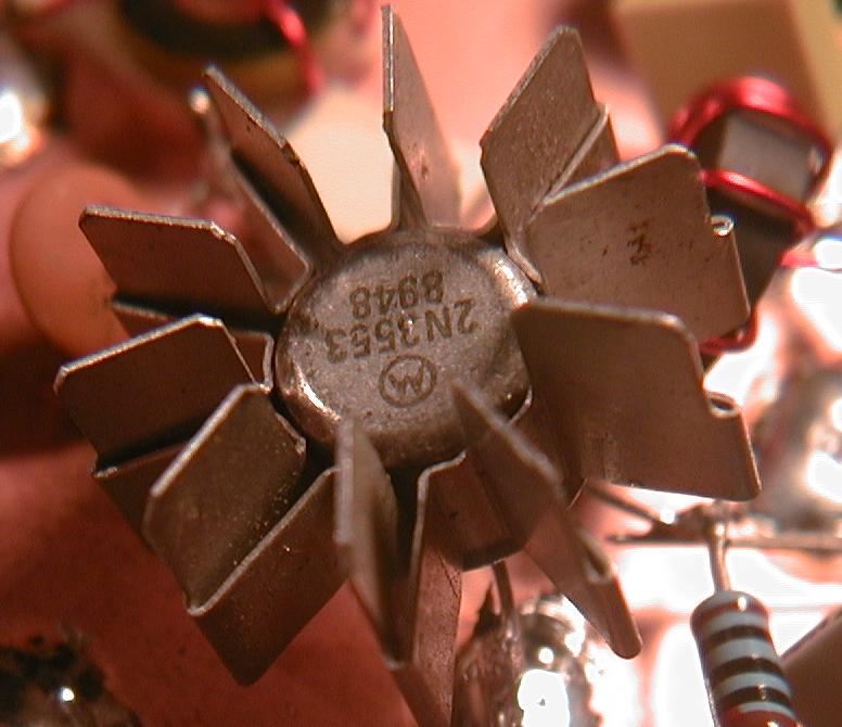
a bit strange though. Added a 2N3866 output transister and BAM! 200 mWatts of 28.060; tweaked the driver
a bit; found a bad connection; changed output transistor to 2N3553. Now we have 250 mW at 9 VDC, 500 mW
at 12 VDC and a full Watt at about 14 VDC. Found a small amount of 20.000 mhz and 8.064 Mhz garbage on
the main signal; may add trap filters later. Also found that if the load goes over 100 ohms, the xmtr
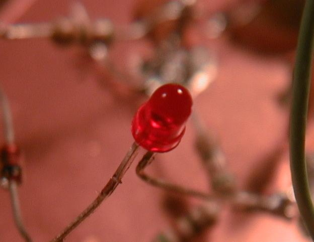
becomes unstable, sooo I added an SWR indicator that can be switched into the transmitter output circuit.
The indicator is an LED and signal diode connected across a balanced bridge network (3 * 50-ohms & antenna).
Pictures of the prototype transmitter are now on our web site. Schematics to follow.
1999-AUG-21
Yesterday I did a little research on the 8.064 xtal. Can only find one manufacturer for it. International
Crystal. Called them, said they had 350 pieces in stock. Also TechAmerica sells these xtals for I.C. at
the same price; $1.16 each in quantity of 100; they had about 75 in stock.
As a side note, there is an 11.059 xtal that is used in digital circuits, VERY COMMON VALUE. If I could
only find a 17.000 MHz xtal that was stock, we would have an alternative mixing scheme.
I ordered more T-37-6 iron powder toroids. Also ordered FT-37-43 and FT-37-61 ferrite toroids for the xmtr
section. Not sure which one to use at 28.06 MHz. I think the 61 material may exhibit less heating losses.
BACK TO THE MIXER FILTER DESIGN.
1999-AUG-20
Last night I built a second VXO and transmit mixer. Results vere virtually identical to the first
VXO/mixer. Freq range 28,055.5 to 28,061.5 with 28,060 at the 11 o'clock position on the pot.
Not happy with the mixer output filter. Will finish the filter and 28,060 low level amp this weekend.
TONIGHT I'M DOING NOTHING BUT - PARTY...
1999-AUG-19
5 AM - 40 meters is dead! Go to Work!
Yesterday, I checked with TechAmerica to verify that the 8.064 xtal is a standard stock part. They said
that it was and had 78 pieces in stock. Manufactured by International Crystal.
Will spend the day getting familiar with DesignWorksLite schematic drawing software.
1999-AUG-18
Ordered 10 more 8.064 xtals & 10 each 20 MHz xtals from TechAmerica via UPS ground!
Took 8.064 xtal # 10 and a generic 20 MHz xtal I had in my stock and build the VXO front end
for the xmtr and rcvr. WOW!!! So far, looks like the freq coverage (using a 10K pot for VXO tune))
will be from 28,055,890 Hz to 28,063,180 Hz with 28,060,000 EXACTLY at midpoint on the potentiometer!
The circuit so far is a FET 20 MHz VXO tuned by a 10K linear pot. The VXO signal is fed to the input
of the transmitter mixer and the oscillator input to the receiver mixer. Both mixers are NE602/SA602.
The result is, I REPEAT ... with the 10K vxo pot in center position, the transmitter mixer output is
EXACTLY 28,060 KHz. Next step is to build another pcb and replicate the results.
1999-AUG-17 (started project)
Started logging design considerations and testing of miniPIG-10. Received 10 each 8.064 MHz crystals from
TechAmerica at a cost of $1.32 each, available at $1.16 in quantity of 100.
Built a simple FET test oscillator to measure and compare xtal frequencies. results were as follows:
xtal #1 - 8,063,760 Hz
xtal #2 - 8,063,895 Hz
xtal #3 - 8,063,897 Hz
xtal #4 - 8,063,779 Hz
xtal #5 - 8,063,710 Hz
xtal #6 - 8,063,827 Hz
xtal #7 - 8,063,830 Hz
xtal #8 - 8,063,873 Hz
xtal #9 - 8,063,844 Hz
xtal #10 - 8,063,915 Hz
Not sure what the maximum deviation should be for a ladder filter (assume 50 Hz).
Should be able to find more matched sets for the ladder filters after I get more xtals.
Started design of the VXO. Looks like FET osc.