Frequency Standard/Reference Kit - SOLD OUT
PDF Instructions [826K] courtesy of Jon, EA2SN


PDF Instructions [826K] courtesy of Jon, EA2SN


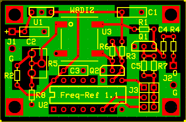
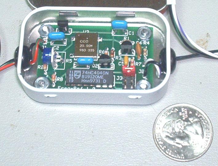
Instructions for building the FREQUENCY STANDARDINVENTORY all the parts against the parts list. ___ 220p CAP 1 C5 ___ 1n 1 C4 ___ 100n 3 C1 C2 C3 ___ 6 pin header 1 J3 ___ jumper 1 RED ___ PCB 1 PCB ___ 51 1 R4 ___ 510 1 R1 ___ 1k 1 R3 ___ 4k7 1 R7 ___ 22k 1 R8 ___ 30k pot 1 R5 ___ 51k 1 R2 ___ 68k 1 R6 ___ 2N3904 2 Q1 Q2 ___ 74HC4040 1 U2 ___ 78L05 1 U1 ___ TCXO 20 MHz 1 U3 ____ Remove the 74HC4040 chip from the DIP socket on the PCB ____ Remove the 16 pin DIP socket from the PCB ____ Remove any residual Aluminum foil ____ Install the TCXO, matching the DOT on the PCB with the TCXO Place (melt) a very small amount of solder on one of the TCXO pads on the PCB, not the TCXO. Place the TCXO on the Pads and solder that pad in place. Solder the remaining pads of the TCXO. INSTALL ALL FIXED RESISTORS ____ R4 51 Green-Brown-Black-Gold ____ R1 510 Green-Brown-Brown-Gold ____ R3 1K0 Brown-Black-Red-Gold ____ R7 4K7 Yellow-Violet-Red-Gold ____ R8 22K Red-Red-Orange-Gold ____ R2 51K Green-Brown-Orange-Gold ____ R6 68K Blue-Gray-Orange-Gold INSTALL ALL CAPACITORS ____ C5 220p labeled 221 ____ C4 1n labeled 102 note: Straighten the pins on the blue 100n capacitors and mount flush on the PCB ____ C1 100n labeled 104 ____ C2 100n labeled 104 ____ C3 100n labeled 104 INSTALL THE 3x2, 6 PIN HEADER ____ J3 6 pin header INSTALL THE IC1. - This IC is STATIC SENSITIVE. ____ xx Install Socket for U2 ____ U2 Insert the 74HC4040 IC into the socket INSTALL Transistors and Voltage Regulator Push the next 3 devices about half way thru the PCB ____ U1, 78L05. match package outline with PCB ____ Q2, 2N3904. match package outline with PCB ____ Q1, 2N3904. match package outline with PCB INSTALL BLUE POT. Note: This is a single turn pot. Good enough for calibration. The PCB has holes for a multiturn pot. You supply. ____ R5 Install the blue 50K (30K on schematic) pot INSTALL POWER AND SIGNAL WIRES. ____ Solder power supply wires (yours) labeled "+" and "G" at J1 Note that power supply voltage range is +7 to +15 VDC ____ Solder RF output wires (yours) labeled "O" and "G" at J2 Use a twisted pair of wires or small coax like RG174 ____ Place red jumper over top 2 pins near C5 and R7 (10 MHz setting) The middle pins are for 2.5 MHz and lower for 5 MHz. Select whichever you want, but for calibration use 10 MHz. CALIBRATE THE FREQ REF (using a WWV Receiver) ____ Set a receiver to WWV on either 10 or 20 MHz. 20 MHz is best for daylight reception and 10 MHz is best at night. Not sure about the UK or Europe. Power up the Freq Ref. Observe polarity. Use a 9v battery or a 12 volt source. Let the reference stablize for 2-3 minutes. If you hear WWV in your receiver, also listen for the Freq Ref. It should be within 1 KHz from WWV. If you can't hear it, verify that your Freq Ref is working with an oscilloscope. Zero beat WWV with the Freq Ref signal by adjusting R5 until the heterodyne is beating at less than 1 Hz per second.
