PigRig Version 2
All updates are in the
Addendum Section
 Build this 5 Watt Single Frequency Transceiver for $42
Full 5 Watts output on 40 or 80 meters using 13.6 VDC
Frequencies available are 7030.7, 7122 and 3561 KHz
Full QSK, one Sideband only, Single Conversion Design
Includes built in keyer IC
The purpose of this new transceiver is to ...
"Provide a high quality, inexpensive transceiver that encourages special groups of hams to communicate with minimal effort."
This transceiver was designed for Radio Clubs and/or Special Events.
You turn the radio on...you listen...you do not tune...you do not switch anything...you do not search.
If you hear someone on "your special frequency", there is a good chance it could be a member of your group.
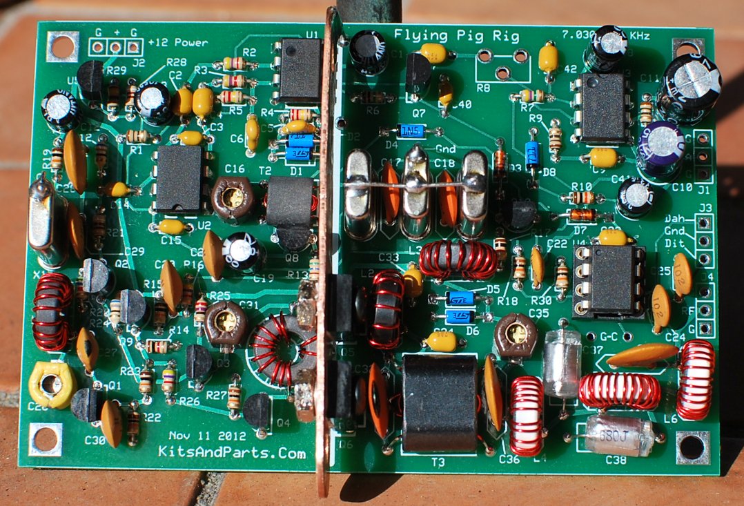
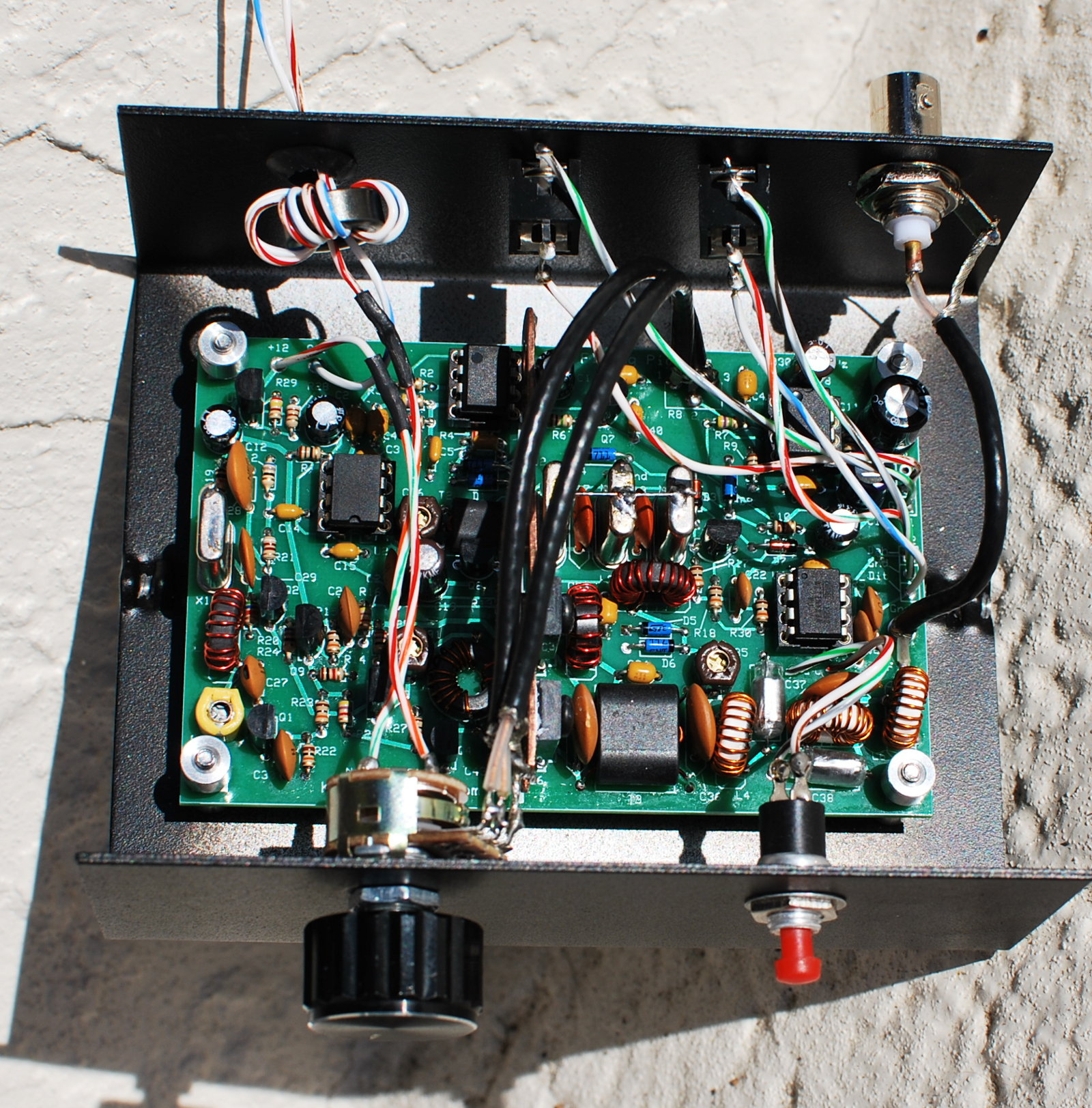
The size of the PCB is only 2.5" (63,5 mm) by 3.8" (96,5 mm), and Yes...it does produce a full 4.99 watts RF out
and it is as sensitive as just about anything else that you may have in your radio shack.
You can customize pigrig frequencies for your club/group; 40 and 80 meters only.
The name of this radio shall henceforth be labeled "The Flying Pig Rig".

Building Instructions:
DO NOT REMOVE ANY PARTS FROM THE PLASTIC BAGS UNTIL INSTRUCTED TO DO SO
1. Inventory all Parts. Some parts like the SMT capacitors will include some extra pieces in case you drop one (lost forever)
Do not mix up the toroids between the plastic bags.
Parts List
If you are missing any parts, contact me immediately. I and will ship the parts the same day.
This kit includes all electrical parts to create a functioning transceiver, including
2 phone jacks, a bnc jack, a push-button, volume/on-off switch, magnet wire, heat sink mounting screws and nuts.
This kit uses four (4) all black ferrite toroids. One (1) FT37-43 and three (3) FT37-61 toroids; they look the same.
The FT37-43 is included in the bag with the 1/8 watt resistors and crystals.
The 0.51 ohm 2 watt power resistor is used to install and support the heat sink
Install the parts in the order per this document to prevent mechanical installation problems later.
Each PigRig is provided with a Serial Number, which is attached to the bag holding the PCB and 26 ga wire
Attach the label to the rear of your PigRig enclosure or wherever suitable
The Serial Number may later be used for tracking in PigRig QSO contests.
This kit requires the following items to complete the kit:
hook-up wire/coax to connect the controls to the printed circuit board (PCB)
Heat sink compound for the RF Finals (Radio Shack Catalog #: 276-1372)
Flat head hammer or similar tool to fabricate the heat sink
1/8th inch drill bit and a drill to create mounting holes for the heat sink
This document has specific instructions for both 40 and 80 meters.
Unique instructions for a specific band will be prefixed with (40M) or (80M)
Any Addendums will be listed by date at the end of this document
2. Install all SMT capacitors
These capacitors are easy to install, especially if you have some kind of part holding/positioning tool.
I made one out of a 1/4 inch metal rod and filed a small slot into the rod to hold the 1206 size caps.
There are 13 pieces 100n capacitors on the PCB; 2 caps, C33 & C34 must use the SMT caps for proper decoupling.
The remaining 100n caps may use the SMT caps or the 100n disks. Recommend you install the SMT caps.
____C33,34: size 1206 SMT 100n capacitors
____C2,3,4,7,9,15,23,40,42,43,46: size 1206 SMT 100n capacitors or 100n disks labeled 104
If you do not install the SMT caps, then the disks can be installed later.
3. Install all 1/8 Watt Resistors.
You will need a magnifying device to verify the resistor color codes.
Be careful not to mix up the one 1K and the 10K resistors.
Bend the resistor leads a sharp 90 degrees from the body of the resistors.
The volume control R8 is installed last.
Save 3 cut resistor leads for use later to ground the crystal cases.
____R1,9,11: 10 Brown-Black-Black-Gold
____R2,3,16,26: 4K7 Yellow-Violet-Red-Gold
____R4,5: 220K Red-Red-Yellow-Gold
DO NOT INSTALL R31 AT THIS TIME. It may or may not be installed to adjust sidetone volume later.
____R6,31: 1M Brown-Black-Green-Gold
____R7,31: 4M7 Yellow-Violet-Green-Gold
R8, the 10K pot/switch will be installed later.
____R12: 68 Blue-Gray-Black-Gold
____R13: 1K2 Brown-Red-Red-Gold
____R14: 1K Brown-Black-Red-Gold
____R10,15,17,18,19,22,23,27,30: 10K Brown-Black-Orange-Gold
____R20: 5K6 Green-Blue-Red-Gold
____R21,28: 910 White-Brown-Brown-Gold
____R29: 240 Red-Yellow-Brown-Gold
The next 4 resistor values depend upon the band of operation.
____R24 (40m): 68 Blue-Gray-Black-Gold
____R24 (80m): 100 Brown-Black-Brown-Gold
____R25 (40m): 27 Red-Violet-Black-Gold
____R25 (80): 100 Brown-Black-Brown-Gold
4. Prepare inductor L2.
Remove the FT37-43 toroid from the packet that contains the crystals.
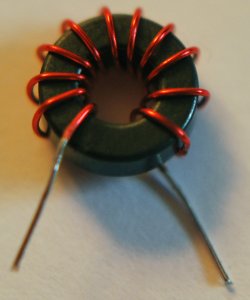
____L2: Wind 11 turns of 26 GA red magnet wire on an FT37-43 ferrite toroid, evenly spaced.
Cut 12 inches of 26 GA wire. Wind the wire on the toroid clockwise.
Trim the wires of L2 to a half inch each.
Strip the insulation to the base of the toroid using a hot solder pencil
This part will be installed later.
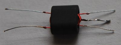
5. Install transformer T2 (small binocular in small plastic back including 34 ga wire).
T2 xfmr is a BN-61-2402 binocular core threaded with fine 34 GA magnet wire.
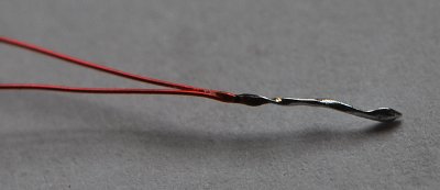
____Cut 10 inches (25 cm) of 34 GA red magnet wire and fold the wire in half.
Using needlenose pliers, grip the wire at the fold and tightly twist
from the folded end for about 1/3 inch (1 cm), about 5 or 6 tight twists
Tin the twisted part of the wire using solder and hot solder pencil.
The plastic insulation will melt and the solder will tin the wire after
applying heat and solder for about 10-15 seconds.
Move the solder pencil back and forth to generate a little friction on the wire.
Insert the wire ends thru the binocular holes.
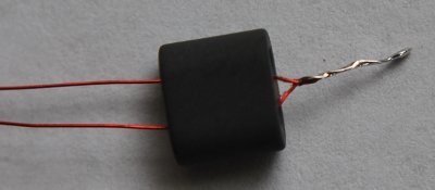
Insert each wire end thru the opposite hole.
We now have two (2) full turns with a center tap.
Repeat 6 more times for a total of 8 full turns.
A full turn is defined as a wire going thru both holes of the binocular.
Trim the wire ends to about 1/2 inch and tin with solder.
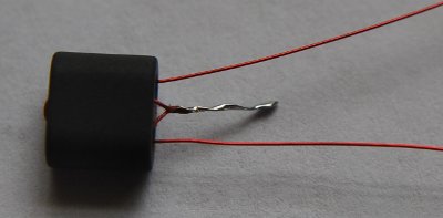
____Cut 4 inches (10 cm) of 34 GA red magnet wire and fold the wire in half.
Insert the wire ends thru the binocular holes as pictured
Insert each wire end thru the opposite hole and tighten the turns
This creates two full turns. Cut to 1/2 inch each and tin.
This is what T2 should look like.
Insert T2 into the top of PCB and solder on the bottom, trimming excess leads.
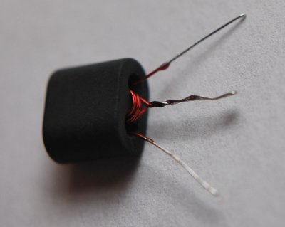
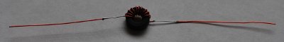
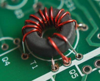
6. Install transformer T1. This xfmr is an FT37-61 toroid with
10 turns primary and 2 turns secondary, centertapped (40 meters) or
11 turns primary and 2 turns secondary, centertapped (80 Meters)
____Cut 9 inches (23 cm) of red 26 GA magnet wire and tightly wind 10 or 11 turns on the toroid.
Wind T1 toroid in a clockwise direction - Generic Toroid Winding Example
Prepare the toroid wires for soldering
____Cut 4 inches (10 cm) of red 26 GA magnet wire and fold the wire in half.
Using needlenose pliers, grip the wire at the fold and tightly twist
from the folded end for about 1/3 inch (1 cm), about 5 or 6 tight twists
Tin the twisted part of the wire using solder and hot solder pencil.
Using solder and a solder pencil, tin 1/2 inch of each wire, about 1/2 inch away from the twist junction.
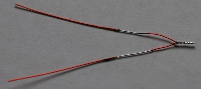
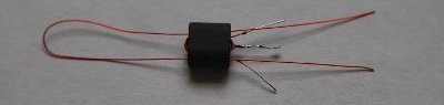
Install the wire by inserting the twisted end into the PCB as shown. Solder and trim.
The insert location is immediately to the left of the Q5 label on the PCB (center tap hole)
Insert one of the free wire ends thru the toroid as shown.
Insert the 10/11 turn wires into their installation holes, leaving about 1 inch slack above the PCB.
Bring the wire that is protruding thru the top of the pcb over and around the toroid and insert the end into the hole above the center tap hole.
Bring the other open wire over and down thru the toroid and insert into the hole below the center tap hole.
Slowly, tighten the wires and pull the toroid down to the PCB, by alternating pulls on the 4 unsoldered wires.
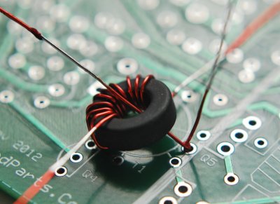
When the toroid is mounted flush on the PCB, solder and clip leads.
Make sure that ALL the leads going thru the holes are tinned and ready for soldering.
7. Install transformer T3.
This xfmr uses the larger BN-43-302 binocular,
2 turns primary centertapped and 2 turns secondary for 40 meters or
4 turns primary centertapped and 4 turns secondary for 80 meters.
T3 is made just like T2 except for wire length and turns.
Cut 5"(40m) or 9"(80m) of 26 GA wire and create a 2(40m) or 4(80m) turns primary centertapped.
Cut 4"(40m) or 8"(80m) of 26 GA wire and create a 2(40m) or 4(80m) turns secondary.
Install into the PCB, tighten all wires, solder and trim leads.
8. Install all ICs and one IC socket.
A socket is included for the Keyer Chip Only. You may optionally provide your own
sockets for the other ICs but that is not be necessary nor is it required
It is possible to reprogram/replace the keyer chip in the future
____U5: LM317L voltage regulator; note orientation on the PCB
____U4: Install the 8 pin IC socket at U4 with the notch pointing up towards C23
____U4: Insert the ATmel ATtiny keyer chip into U4 socket, the dot positioned towards C23
____U1: NE5534AP with the dot pointing to the upper edge of the PCB
____U2: NE602A with the dot pointing to the LOWER edge of the PCB towards C16
____U3: LM-386N-4 with the dot pointing to the upper edge of the PCB
9. Install all Diodes.
____D3,7: 1N4148 red glass diodes
____D1,2,4,5,6,8: 1N5711 blue glass diodes
10. Install all Crystals and 2 capacitors.
When installing the crystals, tilt the crystals while soldering
This will raise the crystal a small bit above the PCB
and will prevent trace shorts to the case of the crystal
____X1: 7031 or 3561 or 7122 crystal with a black mark on one side
____X2,3,4: 7031 or 3561 or 7122 without the black mark (highly matched and quality checked)
____C17,18: 470p (471J) tan disk caps; install between the crystals.
Solder one resistor lead accross the top of all 3 crystals in the filter
Solder one resistor lead from the top of X3 to the ground below
Solder one resistor lead from the top of X1 to the ground below
11. Install all remaining capacitors.
Do not install C32. It will be installed later.
____C1,12,13,41: 33uF black electrolytic - observe polarity
____C2,3,4,7,9,15,23,40,42,43,46: 100n disks labeled 104 (if SMT not installed)
____C5,6: 220p (221) small yellow caps
____C8,19: 10uF black electrolytic - observe polarity
____C10: 47uF black electrolytic - observe polarity
____C11: 470uF black electrolytic - observe polarity
____C14: 47n (0.047uF) small yellow cap
____C16,31,35: 60p brown trimmer caps - flat side into square hole
____C20,21,30: 10n (103) yellow disc or box caps
____C22: 22p (22J NPO) dark tan disk cap
____C24,25: 1n (102) dark tan disk cap
____C26: 40p yellow trimmer cap - flat side into square hole
____C27: 18p(40m) NPO or 47p(80m) NPO (this cap provides the xmit-rcve freq offset)
____C28: 220p(40m) 221J or 470p(80m) disk cap
____C29: 150p(40M) 151J or 100p disk cap
____C32: 270p(40M) DO NOT INSTALL AT THIS TIME
____C36,39: 270p(40m) (271J) or 470p(80m) (471) dark tan disk cap
____C37,38: 680p(40m) poly/disc or 1200p(80m) polystyrene cap
____C44: 82p(80M) disk cap
____C45: 270p(80M) disk cap
12. Install all Transistors except the RF power amps
____Q1,2,8: 2N3904
____Q3,9: 2N3906
____Q4,10: 2N7000
____Q7: J113
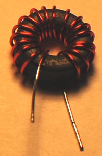
13. Wind and install all remaining Toroid Inductors except L2.
L1 & L3 for 80 meters will use 27 ga green wire, not the larger 26 ga.
____L1: For 40 meters, wind 17 turns of 26 GA red magnet wire on an FT37-61 ferrite toroid, evenly spaced.
____L1: For 80 meters, wind 24 turns of 27 GA green magnet wire on an FT37-61 ferrite toroid, evenly spaced.
For 40 meters, cut 11" of 26 GA wire. Wind the wire on the toroid clockwise.
For 80 meters, cut 15" of 27 green GA wire. Wind the wire on the toroid clockwise.
Trim the wires of L1 to a half inch each.
Strip the insulation to the base of the toroid using a hot solder pencil
Install into the PCB, pull the leads tight using needle nose pliers, solder and trim
You should be able to straighten the toroid to match the outline on the PCB
____L3: For 40 meters, wind 18 turns of 26 GA red magnet wire on an FT37-61 ferrite toroid, evenly spaced.
____L3: For 80 meters, wind 27 turns of 27 GA green magnet wire on an FT37-61 ferrite toroid, evenly spaced.
For 40 meters, cut 11" of 26 GA wire. Wind the wire on the toroid clockwise.
For 80 meters, cut 15" of 27 green GA wire. Wind the wire on the toroid clockwise.
Trim the wires of L3 to a half inch each.
Strip the insulation to the base of the toroid using a hot solder pencil
Install into the PCB, pull the leads tight using needle nose pliers, solder and trim
You should be able to straighten the toroid to match the outline on the PCB
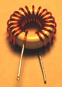
____L4,6: For 40 meters, wind 20 turns of 26 GA red magnet wire on an T37-7 white toroid, evenly spaced.
____L4,6: For 80 meters, wind 20 turns of 26 GA red magnet wire on an T44-2 red toroid, evenly spaced.
Cut 12" (40m) or 15" (80m) of 26 GA wire. Wind the wire on the toroid clockwise.
Trim the wires of L4,6 to a half inch each.
Strip the insulation to the base of the toroid using a hot solder pencil
Install into the PCB, pull the leads tight using needle nose pliers, solder and trim
You should be able to straighten the toroid to match the outline on the PCB
____L5: For 40 Meters, wind 23 turns of 26 GA red magnet wire on an T37-7 white toroid, evenly spaced.
____L5: For 80 Meters, wind 22 turns of 26 GA red magnet wire on an T44-2 red toroid, evenly spaced.
Cut 13" (40m) or 16" (80m) of 26 GA wire. Wind the wire on the toroid clockwise.
Trim the wires of L5 to a half inch each.
Strip the insulation to the base of the toroid using a hot solder pencil
Install into the PCB, pull the leads tight using needle nose pliers, solder and trim
You should be able to straighten the toroid to match the outline on the PCB
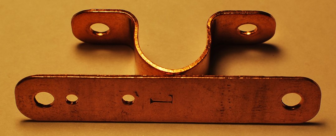
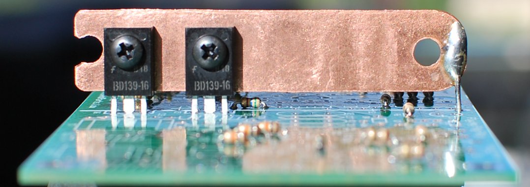
14. Prepare the Copper Heat Sink & Install the RF Final Transistors.
This Kit uses a custom pure copper heat sink that will require preparation.
If the kit contains a Copper pipe clamp, flatten the Copper pipe clamp using your hands,
a vise, and a flat head hammer.
Hammer it until it is totally flat; may take a few minutes, but Copper is soft.
With a pen, mark 2 drill holes exactly 0.5 inch and 1.0 from one end, centered from top/bottom.
If you have a punch, punch the copper at the marks for easier drilling accuracy.
Drill 2 holes using an 1/8 inch drill bit to accommodate a size 4-40 screw.
Deburr the holes using a larger drill bit or other hard tool.
The heat sink will extend about 0.15 inches from the lower edge of the PCB
If you wish, cut of the excess copper per the picture; file/sand/deburr.
Cut one lead from the 5R1 power resistor. Solder to the end of the heat sink per picture
This will require quite a bit of heat from your soldering tool
____Q5,6: BD139-16 Loosely mount the RF Finals to the Heat Sink using the nuts and screws provided,
Make shure that the part number (BD139-16) is visible, facing to the right, away from the heat sink.
Apply a little heat sink grease between the heat sink and the finals.
Fully insert the assembly into the Q5 and Q6 labeled locations.
If you have an IC socket installed at U1, then the assembly should be raised about 0.2 inches
or enough so that the heat sink does not short to pins 5-8 on U1.
Solder both transistors and the cut resistor lead, per the patern on the PCB
all the time keeping the heat sink parallel to the PCB.
____L2: Locate the previously prepared toroid with the 11 turns red magnet wire.
Install into the PCB, pull the leads tight using needle nose pliers, solder and trim
You should be able to straighten the toroid to match the outline on the PCB
____C32: For 40 meters only, 270p (271J) NPO dark tan disk cap; install between the finals and T3.
15. Connections.
BEFORE YOU APPLY POWER TO THE PIGRIG...
Make sure your power polarity is correct
else you will be replacing ICs and the Finals
Recommend chassis/enclosures (Black Color) for the PigRig are from
Ten-Tec
The TP/TPB/TPC-19 ($7.81) and TP/TPB/TPC-41 ($9.15) are ideal for this project.
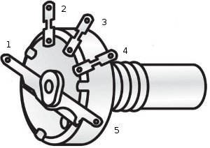
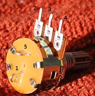
Connect the 10K volume pot w/switch to R8 via your shielded audio cable
Using one shielded cable, connect the inner conductor from R8(2) to pin-3 on the volume control
Connect the cable ground shield to R8(3) and pin-2 on the volume control
Using a second shielded cable, connect the inner conductor from R8(1) to pin-4 on the volume control
Connect the cable ground shield to R8(3) and pin-2 on the volume control
Connect a Speaker or Headphones to J1 via one of the 3.5 mm phono connectors
Connect an Antenna to J4 via the provided BNC connector or connect your own RF output connector
Connect paddles or a straight key to J2 via the other 3.5 mm phono connector
Connect the Push Button Switch via 2 wires to the PCB holes below pins 4 and 5 of U4, labeled "G-C"
Connect +13V volts (+/- 1 volt) to the holes in the upper left corner of the PCB.
If you live near AM broadcast stations, you should install a common mode choke in the 12V power wires.
Make a choke using the FT50-75, half inch diameter black toroid with 5 turns of dual 26 gauge wires.
Do not let the power supply ground connect directly to any metal box ground
The power supply ground must connect to the PCB/chassis through the choke only.
A 1/4 inch Rubber Grommet is included to protect power wires running through a chassis/enclosure wall.
16. Transmit Frequency Alignment using a Frequency Counter or a Calibrated Accurate Receiver
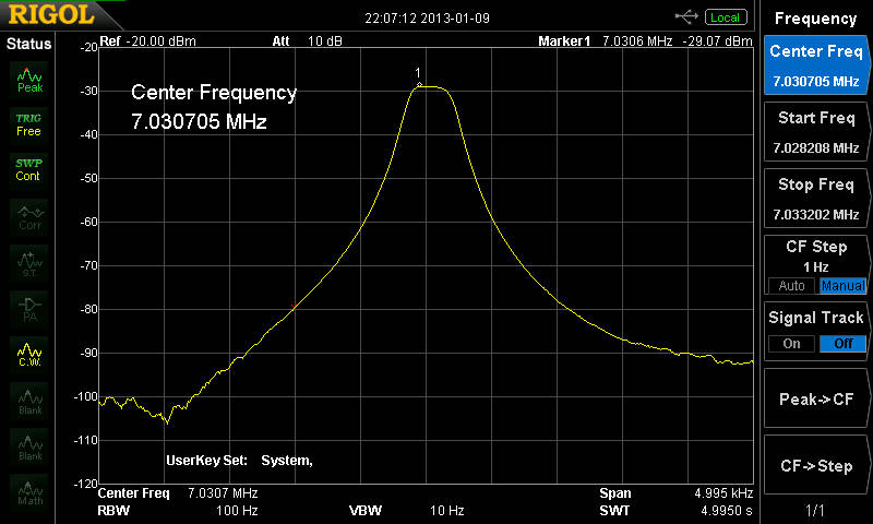
The CENTER FREQUENCY of the front end crystal filter (X2,3,4) is 3,560,880 Hz +/- 40 Hz or ...
the center frequency of the front end crystal filter (X2,3,4) is 7,030,700 Hz +/- 40 Hz or ...
the center frequency of the front end crystal filter (X2,3,4) is 7,121,850 Hz +/- 40 Hz or
We need to adjust our Transmit Oscillator to that frequency by adjusting the yellow trimmer capacitor C26 on the left side of the PCB
Connect a 5 watt or greater 50 ohm dummy load to the antenna connector. Connect a frequency counter to the RF ouput.
Apply 10 (ten) Volts DC power...this prevents damage to the finals in case there is an error with the binocular ferrite.
Most Freq Ctrs are sensitive enought to measure the RF ouput by connecting the FC probe onto anything metallic on/near the dummy load.
if this is not the case, connect the FC directly to the RF output, or through a small coupling capacitor, less than 10 pF.
Place the keyer into straight key mode (see below) and key the transmitter; adjust C26 for the center frequency +/- 10 Hz
If you do not have a frequency counter, use a calibrated accurate receiver, setting the receive freq to the center frequency listed above.
Place the keyer into straight key mode and key the transmitter; adjust C26 for an audio freq of 600 Hz +/- 25 Hz coming from your receiver
This completes the transmitter output frequency alignment.
The oscillator switches between receive and transmit modes by including the 18pF or 47pF capacitor C27 in parallel with C26 when in transmit mode.
When C27 is not grounded through transistor Q1, the X1 oscillator frequency is about 600 Hz higher, which provides the receive mode offset frequency.
When a received signal is directly in the middle of the bandpass, you will hear the signal as 600 Hz +/- from the speaker/headphones.
17. Transmit Driver Alignment.
Apply 10 (ten) Volts DC power...this prevents damage to the finals in case there is an error with the binocular ferrite.
Adjust C31 for maximum transmitter output - should be about 1 Watts using 10 Volts DC
If you do not get 1 Watt output, fix the problem before continuing
Apply 13.6 Volts DC and Adjust C31 for maximum transmitter output.
You can use a wattmeter or SWR meter or receiver to adjust C31 for maximum output.
Using 13.6 volts and a 50 ohm dummy load, you should have 5 Watts output (44 volts peak-to-peak on a scope)
This completes the transmitter driver alignment.
18. Receiver Alignment using a CENTER FREQUENCY signal source.
Adjust the input and output tuned circuits connected to the crystal filter (X2,3,4)
Connect any antenna to the Pig Rig. Anything from a 2 foot wire up a large antenna.
Turn on a signal source in the shack. Either a low power transmitter into a dummy load or a sig-gen.
Adjust C16 and C35, back and forth for maximum audio (approx 600 Hz) coming from the speaker/headphones.
The lower the signal level from the source, the easier it is to adjust C16 and C35
It is important to note that the signal source is on the exact CENTER FREQUENCY to optimize the bandpass filter for a narrow bandwidth.
This completes the receiver alignment.
19. Sidetone volume setting.
The sidetone volume is fixed/set by the resistor R31.
Loudest sidetone volume is with R31 not installed.
A lower volume is set with the installation of a 4M7 resistor at R31
The lowest volume is set with the installation of a 1M0 resistor at R31
This completes the sidetone volume adjustment.
The Flying Pig Rig Keyer Instructions
This is a very basic Keyer (ATmel AVR Assembler Source Code available upon request)
On power-Up, the keyer defaults to 15 WPM and a sidetone of 625 Hz and annunciates "OO" (without keying the XMTR)
The internal timing oscillator in the Keyer Chip is an RC oscillator that runs at 9.6 MHz +/- 10 pct Factory Calibration.
Typical accuracy is +/- 5 percent; The accuracy can be impoved to +/- 2 percent if one takes the time to calibrate
the oscillator and reprogram the keyer chip. This procedure is too time consuming for 200 chips but may be OK for you.
The accuracy is typically +/- 5 pct so your sidetone may be off by +/- 5 pct and your keying WPM may also be off.
That means if you set the WPM speed to 20 WPM, you may actually have it set at 19 or 21 WPM; should not be a problem.
The keyer is placed into the "Command" mode by pressing and releasing the Cmd Button.
The keyer has the following commands available after pressing the Cmd Button:
"E" (.) or "T" (-) Toggles between normal keyer and straight key mode, acknowleged by annunciating "S" (for Straight Key Mode) in CW.
The keyer mode is NOT saved on power-down.
"R" (.-.) Toggles between normal and reverse paddles keys, acknowleged by annunciating "P" (for normal paddles) or "X" (for reversed paddles) in CW.
The paddles (normal or reverse) are saved on power-down.
"S" (...) Set keyer speed in WPM. Speed is entered as two numerical digits.
After sending the "S" command, the keyer sends a DIT (e) as a prompt for the first speed character (0-4)
After sending the first speed number, wait for another DIT (e) prompt and send the 2nd number (0-9)
Depending upon what you enter, you will hear a "?" for ERROR or an "R" for a "Roger" acknowlegement.
Valid keyer speeds are 1 to 45 WPM (good luck trying to send/use 1 WPM)
The keyer speed setting is saved on power-down.
"F" (..-.) Sets the sidetone frequency.
After sending the "F" command, the keyer sends a DIT (e) as a prompt for the tone character (0-9)
Depending upon what you enter, you will hear a "?" for ERROR or an "R" for a "Roger" acknowlegement.
The sidetone frequency setting is saved on power-down.
The following table equates the sidetone number with the sidetone frequency:
0 = 1000 Hz
1 = 833 Hz
2 = 714 Hz
3 = 625 Hz
4 = 555 Hz
5 = 500 Hz
6 = 455 Hz
7 = 417 Hz
8 = 385 Hz
9 = 357 hz
To Reset the Keyer to the Default mode, hold the Cmd button active until you hear "OO"
Then immediately release the Command Button, else you will send another Command request.
The PigRig is now finished, ... except for your first QSO. See you on the PigRig Frequencies.
Addendum Section:
Scope Signal Levels Peak-Peak and DC voltages in the Oscillator (40m) - Driver RF chain using 14 Volt DC Supply
| Location | Rcve-DC | Rcve-Sig | Xmit-DC | Xmit-Sig |
|---|
| U2 Pin6 | 5.25Vdc | 280mVrf | 5.24Vdc | 280mVrf |
|---|
| Q2 Collector | 13.5Vdc | 1.4Vrf | 13.25Vdc | 2.0Vrf |
|---|
| Q3 Emitter | 13.9Vdc | 880mVrf | 13.4Vdc | 1.1Vrf |
|---|
| Q3 Collector | 14.0Vdc | 1.2Vrf | .01Vdc | 14Vrf |
|---|
Variable capacitor settings
| Maximum Capacitance | | Midway Capacitance | | Minimum Capacitance | |
|---|
 | |  | |  | |
|---|
2013 Jun 18 - Updated schematic to correct L2 windings from 12 to 11 turns.
2013 Jun 18 - Pictures of a built 80 meter version will be available by June 22.
2013 Sep 24 - Added the word "green" to section 13 for L1 & L3, 80 meter toroids.
If you need an alignment tool for the trimmers, look up "GC 8608" - available at newark.com and onlinecomponents.com
Bandwidth scan of the 3-crystal front end filter.
End of Addendum Section: top