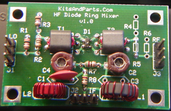
HF Double Balanced Diode Ring Mixer with diplexer for broadband HF coverage from 30 MHz down to 1.8 MHz. Additional wire turns are needed on T1 and T2 for frequency operation below 1.8 MHz
All ports are 50 ohms with optional PI attenuators pads on the RF and LO ports. One 3 dB attenuator is included in the kit.
BUILDING INSTRUCTIONS:
Errors: C3 is NOT installed.
On the schematc, J2(RF Port) should read J3; J3(IF Port) should read J2.
INSTALL the SMD Diode Ring HSMS-2829.
First, using a small flat blade screwdriver, remove the white masking/marking depicting the diode ring SMD on the PCB. We want to make the PCB as flat as possible when mounting the SMD.
Create a tool to hold the SMD in place on the PCB. I used a tooth pick with the tip cut off.
Be careful installing the diode ring. It is very easy for the part to pop out of a holding tool and you end up loosing the part on the floor never to be seen again.
Align the SM device with the PCB mask (note the larger pad on PIN-1) and tack solder one of the pads. Then solder the remaining pads.
If you have a multimeter with a Diode Measure option, you should measure a voltage drop of about 0.56 volts in both directions of pins 1 and 2, and repeat for pins 3 and 4 of the Ring Mixer.
INSTALL RESISTORS:
R1, R2 and R3 are an optional 3 dB attenuator for the local oscillator port. Solder a jumper in place of R2 if not using the attenuator pad.
R4, R5 and R6 are an optional attenuator for the RF port. Solder a jumper in place of R5 if not using the attenuator pad.
R7 and R8 provide a 50 ohm load for both sides of the IF port.
| R1 | 300 | Orange-Black-Brown-Gold | ________ |
| R2 | 18 | Brown-Gray-Black-Gold | ________ |
| R3 | 300 | Orange-Black-Brown-Gold | ________ |
| R7 | 51 | Green-Brown-Black-Gold | ________ |
| R8 | 51 | Green-Brown-Black-Gold | ________ |
Install Transformers.
T1____Cut the two-colored twisted pair wire into three 6-inch pieces.
Using one 6 inch wire pair, Wind 3 turns tight thru T1 without scraping the insulation of the wire. Make sure the wire is twisted about 2 to 3 twists per inch. Cut any excess lead length so that only one (1) inch remains. Strip some of insulation from the wire pigtails up to about 1/16 of an inch from the body of T1. This wire is somewhat heat strip-able but requires some extra heat and time. After the wires are stripped and tinned, twist together one red and one green wire to form a center tap for T1.
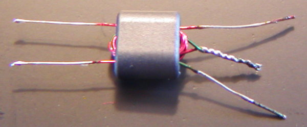
Using another 6 inch wire pair, unwind and serparate the wires. Insert one wire 3 full turns thru T1 holes, trim, strip and tin. T1 transformer should like the picture above.
Install T1 into the circuit board per picture below.
T2____Repeat instruction for T1.
C2____Install 70pF trimmer cap with flat end towards R7
C4____Install 70pF trimmer cap with flat end towards R7
C1____Install 470pF disk
Install any headers you may have now.
L1____Measure out 12 inches or 30 cm from the 26 GA magnet wire and wind 18 turns on black toroid a FT37-61. Trim, strip, tin and install.
L2____Measure out 12 inches or 30 cm from the 26 GA magnet wire and wind 18 turns on red toroid a T30-2. Trim, strip, tin and install.
Toroid Winding Details Here
That's it...all done..here is a picture of the finished product.