INSTRUCTIONS FOR BUILDING THE BPF, A component of the multiPIG+
updated 03/08/03 12:15 PM
The BPF kit includes 5 plastic envelopes and a schematic.
1. BPF PCB
2. Capacitors (do not install until you read special instructions)
3. Toroids
4. Headers
5. Wire
We will build the BPF in this order:
0. Review instructions. Inspect PCB and parts.
1. Install ALL trimmer caps.
2. Wind and install all toroids
3. Install fixed capacitors
4. Install headers
5. Test and align bands
Ready...set...begin!
INVENTORY all the parts against the parts list.
NOTE: For reference, there are two types of trimmer caps.
This is the Yellow Plastic coated version shown with Minimum Capacitance
Note the small dots on the inside of the trimmer.
 This is the White Cermic version shown with Minimum Capacitance
The solder blob is on the right side of the trimmer.
This is the White Cermic version shown with Minimum Capacitance
The solder blob is on the right side of the trimmer.
 ____Install 18 Yellow Trimmers. These are for 10-30 Meters
The flat side of the trimmer goes into the square pad
READ THIS CAREFULLY!
The White Ceramic trimmers need to be "reformed" so that all the
components will fit on the PCB correctly.
Notice the way that the pin on the flat side of the cap is bent inward.
Straighten this pin. Then form the other pin inward. In other words,
reverse the way the pins are shaped.
____Install 12 White Ceramic Trimmers. These are for 40-160 meters.
The flat side of the trimmer goes into the square pad
____Preset all 30 trimmer caps to mid capacitance position
WIND AND INSTALL TOROIDS
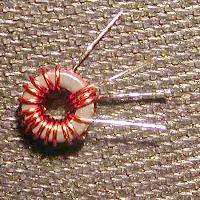
All dual turn toroids should look like this:
note that the picture shows the leads from top to bottom as
wire on bottom, top, bottom, top
____Install 18 Yellow Trimmers. These are for 10-30 Meters
The flat side of the trimmer goes into the square pad
READ THIS CAREFULLY!
The White Ceramic trimmers need to be "reformed" so that all the
components will fit on the PCB correctly.
Notice the way that the pin on the flat side of the cap is bent inward.
Straighten this pin. Then form the other pin inward. In other words,
reverse the way the pins are shaped.
____Install 12 White Ceramic Trimmers. These are for 40-160 meters.
The flat side of the trimmer goes into the square pad
____Preset all 30 trimmer caps to mid capacitance position
WIND AND INSTALL TOROIDS
All dual turn toroids should look like this:
note that the picture shows the leads from top to bottom as
wire on bottom, top, bottom, top
 Use this schematic for the parts below. The numbers are repeated
for each band on the PCB
Use this schematic for the parts below. The numbers are repeated
for each band on the PCB
 Here are the turns and capacitance values for each band:
BAND L1 L2 L3 C2,C5,C7 C3,C6
160M 46T:4T:T37-2 47T:T37-2 46T:4T:T37-2 820pF 12pF
25"#32+4"#32 25"#32 25"#32+4"#32
80M 30T:3T:T37-2 30T:T37-2 30T:3T:T37-2 470pF 6.8pF
17"#28+4"#28 17"#28 17"#28+4"#28
60M 29T:3T:T37-2 29T:T37-2 29T:3T:T37-2 220pF 4.7pF
17"#28+4"#28 17"#28 17"#28+4"#28
40M 27T:3T:T37-2 27T:T37-2 27T:3T:T37-2 130pF 3.0pF
16"#27+4"#27 16"#27 16"#27+4"#27
30M 25T:2T:T37-6 25T:T37-6 25T:2T:T37-6 100pF 2.7pF
15"#27+3"#27 15"#27 15"#27+3"#27
20M 21T:2T:T37-6 21T:T37-6 21T:2T:T37-6 68pF 1.5pF
13"#27+3"#27 13"#27 13"#27+3"#27
17M 18T:2T:T37-6 18T:T37-6 18T:2T:T37-6 43pF 1.0pF
11"#27+3"#27 11"#27 11"#27+3"#27
15M 17T:2T:T37-6 17T:T37-6 17T:2T:T37-6 33pF 1.0pF
11"#27+3"#27 11"#27 11"#27+3"#27
12M 15T:2T:T37-6 15T:T37-6 15T:2T:T37-6 33pF 1.0pF
10"#27+3"#27 10"#27 10"#27+3"#27
10M 14T:2T:T37-6 14T:T37-6 14T:2T:T37-6 none 1.0pF
9"#27+3"#27 9"#27 9"#27+3"#27
INSTALL 3 TOROIDS FOR EACH BAND
____L2
____L1
____L3
INSTALL 5 CAPACITORS FOR EACH BAND
____C2, C5, C7
____C3, C6
ALIGNMENT - We can adjust the BPF in the receive mode, but
it is easier and more accurate to adjust them in Transmit mode.
If you have a scope, you can align the BPF without the XMTR pcb
but this method we will do the alignment with ALL 6 MP+ modules connected.
Interconnect all 6 MP+ modules.
We will align the BPF starting at 160 meters and work up to 10 meters.
Connect a dummy load to the 160 meter output on the LowPassFilter.
Apply 12 volt power to the MP+ via an Amp meter.
Current will be anywhere from 250 ma to 1.5 amps.
Set the PLL to 1810 KHz.
Set the trimer caps C1, C4 and C8 at mid point.
Set the Power Out control R18 on the XMTR at the half way point.
Place the FCC into XMIT mode by shorting pins 1 and 2 on the FCC J2
Make sure that the current is less than half an amp.
Adjust C1, C4 and C8 for maximum current. If the current goes above
one amp, cut it back to half an amp via R18 on the XMTR board.
Repeat the C1, C4 and C8 adjustents until tweaked for max current.
As you perform these adjustment, make sure that Q2 and Q3 on the
XMTR pcb do not get too hot. Too hot means you can't touch them
without feeling some pain.
Turn off the XMIT mode and repeat the above steps for the other band
in this order/freqs:
80 - 3560
60 - 5300
40 - 7040
30 - 10110
20 - 14060
17 - 18080
15 - 21060
12 - 24900
10 - 28060
Note that when the MP+ total current is about 950 ma, you should be
generating about 5 watts output into 50 ohms.
NEED HELP?
Email me ... w8diz at fpqrp.com
Here are the turns and capacitance values for each band:
BAND L1 L2 L3 C2,C5,C7 C3,C6
160M 46T:4T:T37-2 47T:T37-2 46T:4T:T37-2 820pF 12pF
25"#32+4"#32 25"#32 25"#32+4"#32
80M 30T:3T:T37-2 30T:T37-2 30T:3T:T37-2 470pF 6.8pF
17"#28+4"#28 17"#28 17"#28+4"#28
60M 29T:3T:T37-2 29T:T37-2 29T:3T:T37-2 220pF 4.7pF
17"#28+4"#28 17"#28 17"#28+4"#28
40M 27T:3T:T37-2 27T:T37-2 27T:3T:T37-2 130pF 3.0pF
16"#27+4"#27 16"#27 16"#27+4"#27
30M 25T:2T:T37-6 25T:T37-6 25T:2T:T37-6 100pF 2.7pF
15"#27+3"#27 15"#27 15"#27+3"#27
20M 21T:2T:T37-6 21T:T37-6 21T:2T:T37-6 68pF 1.5pF
13"#27+3"#27 13"#27 13"#27+3"#27
17M 18T:2T:T37-6 18T:T37-6 18T:2T:T37-6 43pF 1.0pF
11"#27+3"#27 11"#27 11"#27+3"#27
15M 17T:2T:T37-6 17T:T37-6 17T:2T:T37-6 33pF 1.0pF
11"#27+3"#27 11"#27 11"#27+3"#27
12M 15T:2T:T37-6 15T:T37-6 15T:2T:T37-6 33pF 1.0pF
10"#27+3"#27 10"#27 10"#27+3"#27
10M 14T:2T:T37-6 14T:T37-6 14T:2T:T37-6 none 1.0pF
9"#27+3"#27 9"#27 9"#27+3"#27
INSTALL 3 TOROIDS FOR EACH BAND
____L2
____L1
____L3
INSTALL 5 CAPACITORS FOR EACH BAND
____C2, C5, C7
____C3, C6
ALIGNMENT - We can adjust the BPF in the receive mode, but
it is easier and more accurate to adjust them in Transmit mode.
If you have a scope, you can align the BPF without the XMTR pcb
but this method we will do the alignment with ALL 6 MP+ modules connected.
Interconnect all 6 MP+ modules.
We will align the BPF starting at 160 meters and work up to 10 meters.
Connect a dummy load to the 160 meter output on the LowPassFilter.
Apply 12 volt power to the MP+ via an Amp meter.
Current will be anywhere from 250 ma to 1.5 amps.
Set the PLL to 1810 KHz.
Set the trimer caps C1, C4 and C8 at mid point.
Set the Power Out control R18 on the XMTR at the half way point.
Place the FCC into XMIT mode by shorting pins 1 and 2 on the FCC J2
Make sure that the current is less than half an amp.
Adjust C1, C4 and C8 for maximum current. If the current goes above
one amp, cut it back to half an amp via R18 on the XMTR board.
Repeat the C1, C4 and C8 adjustents until tweaked for max current.
As you perform these adjustment, make sure that Q2 and Q3 on the
XMTR pcb do not get too hot. Too hot means you can't touch them
without feeling some pain.
Turn off the XMIT mode and repeat the above steps for the other band
in this order/freqs:
80 - 3560
60 - 5300
40 - 7040
30 - 10110
20 - 14060
17 - 18080
15 - 21060
12 - 24900
10 - 28060
Note that when the MP+ total current is about 950 ma, you should be
generating about 5 watts output into 50 ohms.
NEED HELP?
Email me ... w8diz at fpqrp.com