Build this 2-30 mHz 5 Watt Output Class-C Amplifier for $29
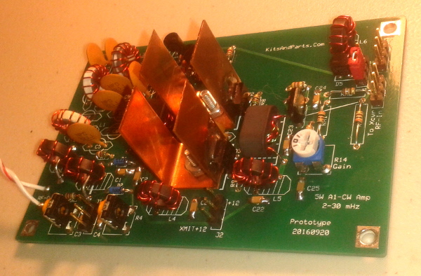
This RF amplifier will boost your low power project to a full 5 watts
Includes PIN Diodes Circuit for Full QSK T/R Switching
Full 5 Watts output from 5 mW to 500 mW input
Includes Forward & Reflected SWR output (using user supplied analog meters)
Includes provisions for a 7 pole Low Pass Filter (user supplied)
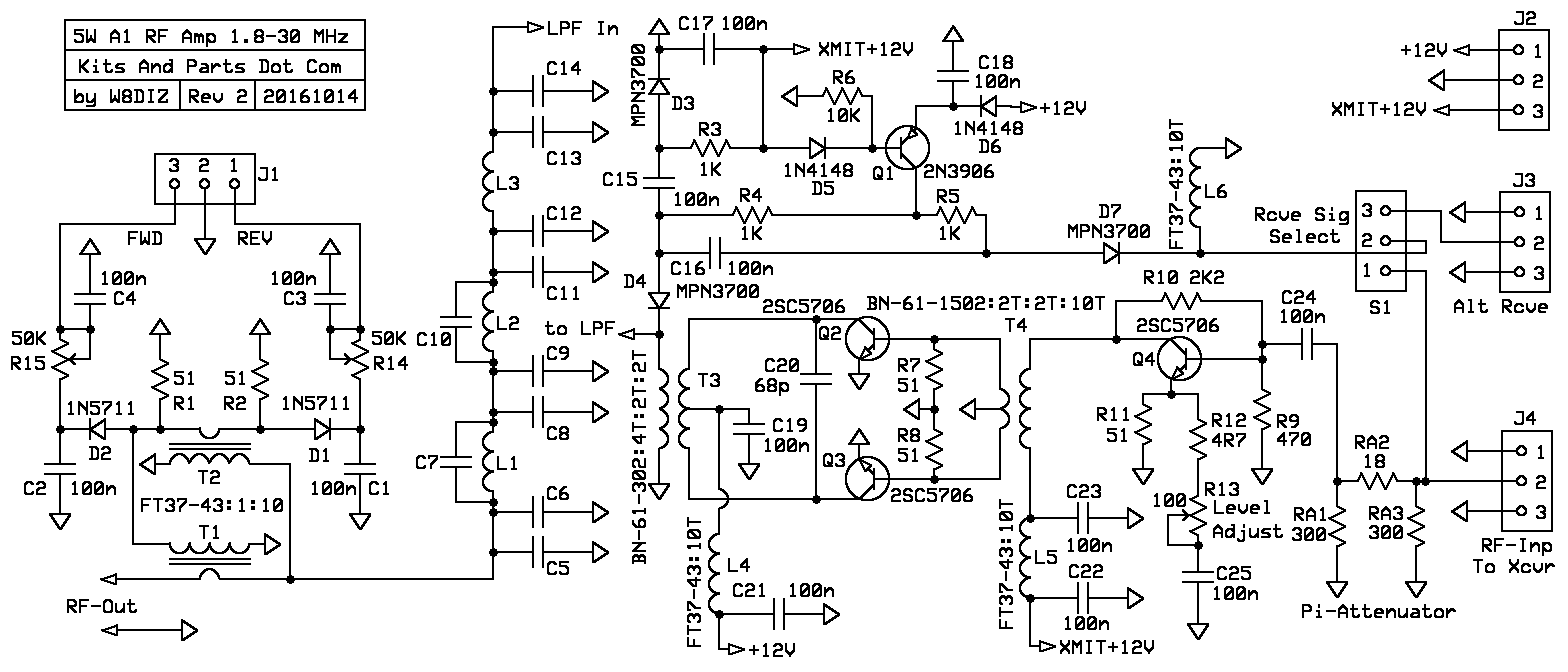
Parts list for The 5 Watt Class-C Amplifier
C1,2,3,4,15,16,17,18,19,21,22,23,24,25 - 100n
C5,6,7,8,9,10,11,12,13,14 (user supplied low pass filter caps)
C20 68p
D1,2 1N5711 blue (two pieces taped together)
D3,4,7 MPN3700 TO-92 PIN Diode
D5,6 1N4148 red
L1,2,3 (user supplied low pass filter inductors)
L4,5,6 FT37-43 with 10 or 14 turns, 10" #26 magnet wire
Q1 2N3906
Q2,3,4 2SC5706
R1,2 51 quarter watt resistors
R3,4,5 1K
R6 10K
R7,8,11 - 51 eighth watt resistors
R9 470
R10 2K2
R12 4R7
R13 100 ohm trim pot
R14,15 50K ohm trim pots
RA1,2,3 300/18/300 ohm 3 dB attenuator resistors
RA1,2,3 150/36/150 ohm 6 dB attenuator resistors
RA1,2,3 100/68/100 ohm 9.5 dB attenuator resistors
T1,2 FT37-43 with 10 turns primary - 9" #26 wire
and 1 turn secondary - 1.5" #20 green wire
T3 BN-61-302 with 4 turns secondary - 8" #26 wire
and 4 turns primary center tapped - 9" #26 wire
T4 BN-61-1502 with 10 turns primary - 10" #26 wire
and 4 turns primary center tapped - 6" #26 wire
Two Copper Heat Sinks for Q2 & Q3
Two 4-40 phillips head screws with nuts
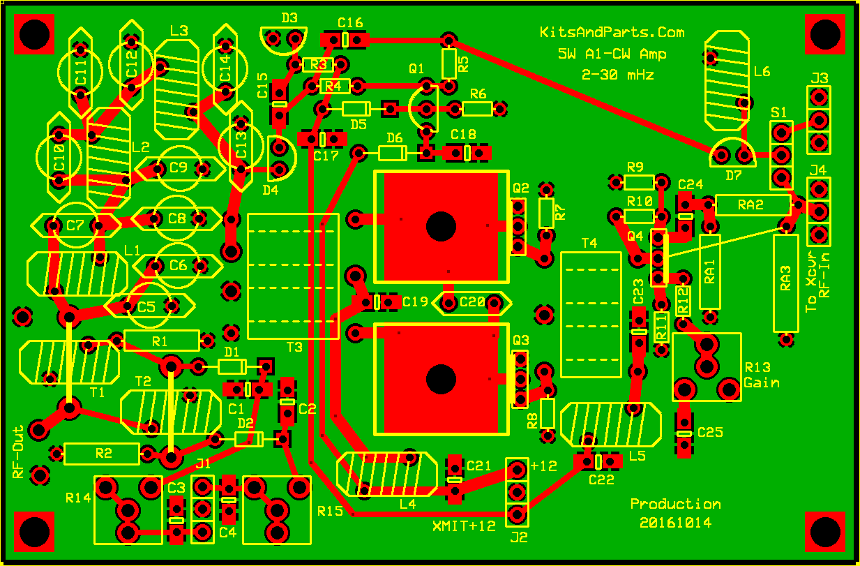
PCB Printed Circuit Board
81" #26 red or green solderable magnet wire (17t)
3" #20 green solderable magnet wire
PCB headers, connectors *NOT INCLUDED*
Case *NOT INCLUDED*
End of Part List
|
Building Instructions:
1. Inventory all Parts
2. Decide if you need to install the Driver Circuit Q4
and/or the PI-Attenuator circuit (user supplied).
Decide if you need to install the PIN Diode antenna switching circuit.
Decide if you need to install a low pass filter circuit (user supplied).
Decide if you wish to install the SWR bridge circuit.
For 5-25 mWatts input, install the pre-amp circuit; do not install the attenuator.
For 25-300 mWatts input, install the pre-amp circuit Q4 and install the attenuator.
For 300-500 mWatts input, do not install the pre-amp circuit Q4; maybe install the attenuator.
We will install the power transistors and heat sinks last.
1. Install all parts for push-pull amplifier Q2 & Q3
____C19,21,24: 100n green caps labeled 104
____C20: 68p disk cap labeled NPO 68J
Bend all 1/8 Watt Resistors leads a sharp 90 degrees from the resistor body
____R7,8: 51R 1/8 watt Green-Brown-Black-Gold
____T3: Wind #26 wire on T3 depending on the band/frequency of use:
A full turn thru a binocular is defined as a wire thru both holes.
160 meters: 8 turns primary center tapped at 4 turns - 14" of #26 Magnet wire
8 turns secondary - 12" of #26 Magnet wire
80-40 meters: 6 turns primary center tapped at 3 turns - 12" of #26 Magnet wire
6 turns secondary - 10" of #26 Magnet wire
30-10 meters: 4 turns primary center tapped at 2 turns - 10" of #26 Magnet wire
4 turns secondary - 8" of #26 Magnet wire
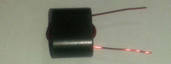
Wind the secondary using #26 wire through a BN-61-302 binocular
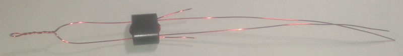
Wind the primary using #26 wire through a BN-61-302 binocular
Fold the wire in half; insert into the binocular per the picture
Leave a 3/4 inch loop; twist the loop per the picture
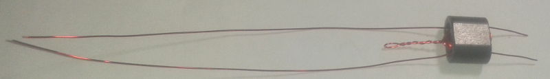
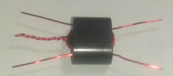
Trim all wires to 3/4 inches; strip and tin the wires using a hot solder pencil and solder
Align and Install T3 on the PCB into the holes per the picture.
Solder and trim leads.
____T4: Wind #26 wire on T4 depending on the band/frequency of use:
A full turn thru a binocular is defined as a wire thru both holes.
160-40 meters: 10 turns primary - 12" of #26 Magnet wire
4 turns secondary, center tapped at 2 turns - 10" of #26 Magnet wire
30-10 meters: 5 turns primary - 12" of #26 Magnet wire
2 turns secondary, center tapped at 1 turn - 10" of #26 Magnet wire
Build this transformer in the same manner as T3
Trim all wires to 3/4 inches; strip and tin the wires using a hot solder pencil and solder
Align and Install T4 on the PCB into the holes per the picture.
Solder and trim leads.
____L4: For 10-40 meters, wind 10 turns of 26 GA wire on an FT37-43 ferrite toroid.
For 80-160 meters, wind 14 turns of 26 GA wire on an FT37-43 ferrite toroid.
Cut 10 inches of 26 GA wire. Wind the wire on the toroid clockwise.
Trim the wires of L4 to a half inch.
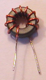
Strip the insulation off the wires using a hot solder iron.
Install and trim leads from the PCB.
For 300-500 mWatts input, place a wire jumper from the
center hole (Collector) of Q4 to the top hole (Base) of Q4
Place a jumper across RA2
Place a jumper across C23
For 25-300 mWatts input, install the preamp/driver circuit Q4
and install the PI-Attenuator circuit (if needed) (user supplied)
PI attenuators with 500 mWatts max input.
R3 is a 1/2 watt resistor. R1 & R2 are 1/4 watt resistors.
The table below shows the percent power dissipation for the pi attenuators.
A 3 dB attenuator will dissipate 50 percent total input power (17%+24%+9%).

             PI attenuator

    Output   -+---RA2---+-   Input
              |         |
             RA1       RA3
              |         |

  dB      RA3       RA2      RA1
 ---   	-------   ------   ------
   3    300/17%   18/24%   300/9%   Included in kit
   4    220/23%   24/29%   220/9%   Not Included
   6    150/34%   36/33%   150/8%   Included in kit
 7.7    120/40%   51/34%   120/7%   Not Included
 9.5    100/50%   68/33%   100/6%   Included in kit
If RF input power is between 30 mW and 60 mW, install the 3 dB attenuator
If RF input power is between 60 mW and 120 mW, install the 6 dB attenuator
If RF input power is between 120 mW and 240 mW, install the 6 dB attenuator
If RF input power is between 240 mW and 300 mW, install the 9.5 dB attenuator
2. Install all parts for for the preamp/driver Q4 (for input power between 5 and 300 mWatts
____C22,23,25: 100n green caps labeled 104
Bend all 1/8 Watt Resistors leads a sharp 90 degrees from the resistor body
____R9: 470 1/8 watt Yellow-Purple-Brown-Gold
____R10: 2K2 1/8 watt Red-Red-Red-Gold
____R11: 51 1/8 watt Green-Brown-Black-Gold
____R12: 4R7 1/8 watt Yellow-Purple-Gold-Gold
____R13: 100 ohm trim pot Green-Brown-Black-Gold
____L5: For 10-40 meters, wind 10 turns of 26 GA wire on an FT37-43 ferrite toroid.
For 80-160 meters, wind 14 turns of 26 GA wire on an FT37-43 ferrite toroid.
Cut 10 inches of 26 GA wire. Wind the wire on the toroid clockwise.
Trim the wires of L5 to a half inch.
Strip the insulation off the wires using a hot solder iron.
Install and trim leads from the PCB.
3. Install all parts for the PIN Diode antenna switching circuit (if needed)
____C15,16,17,18: 100n green caps labeled 104
Bend all 1/8 Watt Resistors leads a sharp 90 degrees from the resistor body
____R3,4,5: 1K 1/8 watt Brown-Black-Red-Gold
____R6: 10K 1/8 watt Brown-Black-Orange-Gold
____D5,6: 1N4148 - red glass diodes
____D3,4,7: MPN3700 - install 1/10 inch or 2,5 mm spacing above the PCB
____L6: For 10-40 meters, wind 10 turns of 26 GA wire on an FT37-43 ferrite toroid.
For 80-160 meters, wind 14 turns of 26 GA wire on an FT37-43 ferrite toroid.
Cut 10 inches of 26 GA wire. Wind the wire on the toroid clockwise.
Trim the wires of L6 to a half inch.
Strip the insulation off the wires using a hot solder iron.
Install and trim leads from the PCB.
____Q1: 2N3906
4. Install all parts for the SWR bridge circuit (if needed)
If you do not install the SWR circuit, you must still install jumpers over T1 & T2
to provide a signal path from low pass filter to RF-Out.
____C1,2,3,4: 100n green caps labeled 104
____R1,2: 51R 1/4 watt Green-Brown-Black-Gold
____R14,15: 50K ohm pots
____D1,2: 1N5711 - install the blue diodes observing polarity
____T1,2: For 10-40 meters, wind 10 turns of 26 GA wire on an FT37-43 ferrite toroid.
For 80-160 meters, wind 14 turns of 26 GA wire on an FT37-43 ferrite toroid.
Cut 10 inches of 26 GA wire. Wind the wire on the toroid clockwise.
Trim the wires of T1,2 to a half inch.
Strip the insulation off the wires using a hot solder iron.
Install and trim leads from the PCB.
Output of the SWR circuit can drive any ampmeter from 50uAmp to 2mAmp
Remove the insulation from the 3 inch green #20 gauge wire
Cut the wire in half
Insert one wire thru T1 and the other wire thru T2
Position the wire into the center of T1 and T2
Solder and trim leads from the PCB.
5. Install the low pass filter circuit (user supplied) (if needed)
If you do not install the LPF circuit, take your RF-Out direct from T3.
| Suggested values for 7 pole low pass filters | |||||||||
|---|---|---|---|---|---|---|---|---|---|
| 160 | 80 | 40 | 30 | 20 | 17 | 15 | 12 | 10 | |
| C5,13 | 1800 | 910 | 470 | 330 | 220 | 180 | 150 | 120 | 120 |
| C6,14 | empty | empty | empty | empty | empty | empty | empty | empty | empty |
| C7,10 | empty | empty | empty | empty | empty | empty | empty | empty | empty |
| C8,11 | 1800 | 910 | 470 | 330 | 220 | 180 | 150 | 120 | 120 |
| C9,12 | 1800 | 910 | 470 | 330 | 220 | 180 | 150 | 120 | 120 |
| L1,2,3 | T37-1 23 turns | T37-1 16 turns | T37-2 16 turns | T37-2 13 turns | T37-6 14 turns | T37-6 12 turns | T37-10 12 turns | T37-10 12 turns | T37-10 10 turns |
6. Install the custom copper heat sinks and Q2 & Q3 & Q4
Insert the 4-40 pan head phillips screws from the bottom of the PCB;
Position the copper heat sinks over the screws, one flat side towards Q2 and Q3
then tighten with washers and nuts.
Using a temperature controlled solder pencil, tin the heat sink adjacent to Q2
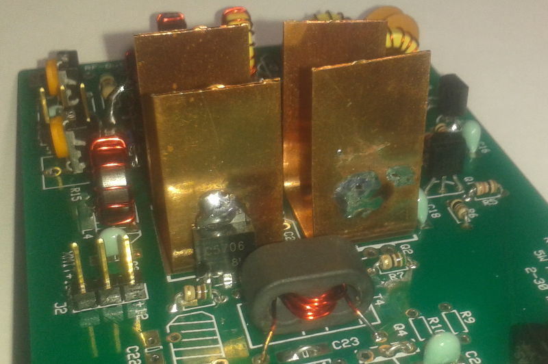
While the heat sink is still very hot, insert Q2 and solder the collector tab to the heat sink.
Repeat with Q3
Install Q4 if preamp/driver is used.
7. Operation using preamp/driver:
Adjust R13 for desired RF output to a 50 ohm dummy load.
8. Operation without preamp/driver:
Adjust RF source power and/or insert pi attenuator at RA1, RA2 and RA3